News:

Obsolete industrial electronics forum is still alive and well, just undergoing some maintenance and more anti spam stuff, stand by for a better experience

Main Menu
Menu

Show posts

This section allows you to view all posts made by this member. Note that you can only see posts made in areas you currently have access to.

Show posts Menu

Messages - alexrodgers

#1
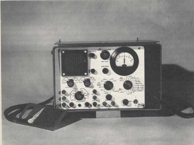
The Proboscope is an electronic test unit with a built-in dual trace oscilloscope and meter specifically designed so that certain test points in the P&W Tape-O-Matic control unit could be examined.

This is definitely a dedicated piece of test equipment for a very old piece of technology. The control units on these old NC machines includes in its design a plug-in card receptacle for the Proboscope connector.


#2
Here is detailed tape reader info from the manual, I'm not sure if this will help you at this point...

GENERAL DESCRIPTION

The Tape Reader is a motor driven device which is capable of reading
tape in either direction at a rate of 60 characters per second. However
a nominal rate of 50 cycles per second has been established for this
machine. As shown in Figure 10-I, the basic mechanism is comprised
of a series of sprockets (free rotating star wheels) which ride on top of the
tape. The points of the star wheel, which drop into the punched tape holes,
actuate the reeds of a switching arrangement which are equivalent to single
pole double throw switches. The tape itself is driven by a clutch operated
capstan (bidirectional) which is controlled by pulse signals from the tape
control system. The motor itself is continuously operated in one direction.

TAPE READ HEAD

As the capstan moves the tape through the read head, the tape is fed and
taken up so a,s to provide approximately 120 degrees wrap on the capstan
(see illustration A & B). This retards elongation of sprocket holes in
tapes that must be read hundreds of times. The strippers on either side
of the capstan prevent the tape from wrapping around the capstan.
Holes in the tape are sensed by the five point star wheels. Spring
pressure applied to the star wheel lever by each movable contact, holds
the star wheel lightly against the tape.


As shown in Figure 10-1, when a no-hole condition is sensed, the star
wheel rides the tape on two of its points, and the movable contact is
switched to the upper, normally closed (N/C) position. When a hole is
sensed (with the tape moving in either direction), one of the star wheel
points drops through the hole and the movable contact is switched downward
to the normally open (N/O) position. Therefore, an electric pulse
delivered to the movable contact wire (common) will be conducted to the
N/C terminal if a no-hole is sensed or to the N/O terminal if a hole is
sensed.

By definition, the normally closed contact (N/C) is that contact which
is closed when the star wheel reads a no-hole condition on the tape.
Similarly, the normally open (N/O) contact is closed when the star wheel
reads a hole in the tape.


MOTOR AND CAPSTAN DRIVE

Drive power is transmitted to the input shaft by a timing belt, and
then to the two clutch assemblies by idler bevel gears. When the tape
is not being moved, an armature on each of two escapement assemblies
engages a tooth of the escapement wheel on the corresponding clutch
assembly, causing the clutches to slip. When the tape is to be advanced
(capstan rotation counterclockwise), an electric pulse energizes the
electromagnet on the forward escapement assembly disengaging the
a,rmature from the escapement wheel and permitting the forward clutch
assembly to rotate . Rotation of the clutch assembly transfers torque
from the clutch through the differential to the capstan shaft. When the
escapement coil is deenergized, allowing the armature to drop and
engage the next tooth of the escapement wheel, the capstan is stopped
in position to read the next character.

ELECTRICAL OPERATION

ESCAPEMENT OPERATION

To advance the tape (capstan rotation counterclockwise), a drive pulse
is a,pplied to the for.ward escapement assembly. The energized
electromagnet disengages the armature from the escapement wheel
allowing the clutch assembly to rotate. Similarly, the tape may be
moved in a reverse direction by pulsing the rever`se escapement
assembly.

SWITCHING ACTION

Switches in each of the 8 channels may be ''read" by introducing a
pulse to the common (Movable) contact. If a pulse is transmitted
throught the normally closed (N/C) contacts to the output, the tape
does not have a hole in that particular read position. On the other
hand, if the pulse is transmitted to the output through the normally
open (N/O) contacts, a hole is sensed.

TIMING

Figure 10-3 shows the timing relationships and pulse duration requirements
of the Tape Reader. To start a cycle, a pulse (as applicable)
4. 5 milliseconds long is applied to either electromagnet which
momentarily disengages the armature from the escapement wheel in
the clutch a.ssembly. The clutch a,ssembly responds immedia,tely, and
the torque transmitted through the differentia,1 rotates the read head
capstan. As the tape is moved over the capstan, it is read by the star
wheels. If holes are read, the movable contacts will be switched from
the normally closed to the normally open position. However, due to
the mechanical delay of the reader, contact switching occurs between 7
and 14 milliseconds after the drive pulse has been applied.

CYCLE LENGTH LIMITATIONS

All the Timing discussion and the Timing Diagram is based on:
Maximum reading rate of 60 characters per second.
Drive motor speed of 1725 I.pin.
Drive pulse of 14 volts amplitude and 4. 5 milliseconds duration.
Under these conditions, the minimum time duration of one cycle is
16. 7 milliseconds, i. e. drive pulses must be at least 16. 7 milliseconds
apart (leading edge to leading edge).

TAPE READER MAINTENANCE

LUBRICATION

loo hours - I drop DC-200 silicon lubricant to each of motor cups.
200 hours - 1 drop DC-200 silicon lubricant to each clutch a.nd hole
in the frame members.
The escape lever fulcrum should be lubricated with moly-cote or its
equivalent. (Lube kit is sold as additional equipment. )

CLEANING

The read head and contacts should be cleaned regularly with a fine
brush and clean cloth. To gain access to the read head, rermove
the one screw on the front of the head cover and withdraw the cover
away from the front panel.

CAUTION: Do not disarrange the small wires of the movable contacts.
IMPORTANT: Keep the star wheels clean and free of dust, lint and
hair, so as to keep free rolling.

PARTS REPLACEMENT

If erroneous readings occur, examine contacts for dirt or pitting.
Replace pitted contacts.

READ HEAD ADJUSTMENT

Reading errors may be caused by incorrect adjustment of the read
head assembly. Check if each of the eight star wheel levers are free
to move in a vertical direction without any drag on the adjacent levers.

DRIVE SYSTEM COMPONENTS

Damaged gear or shafts may be replaced by loosening all set screws
which clamp the gears to the shaft and slide the shaft axially through
the bearings.

CAUTION: Do not disassemble the frame members. Preserve
all the shim washers disassembled. It may be necessary to add
or leave out shims when new gears are installed.

ESCAPE ACTUATORS

An open or shorted coil may cause the escape actuator to become
inoperative. The pivot slot in the pallet lever may also become worn
excessively after long operation. Replace the complete actuator
assembly in either case.


#3
The Maintenance Saloon / Re: Vintage Meter Movements
December 19, 2017, 08:28:PM
I'm going to do some meter movement digging. I know I've got some pretty big meters somewhere in my stuff. I'll post some pics if I can find them.
#4
The Maintenance Saloon / Re: Vintage Machine Tools
December 19, 2017, 08:26:PM
Some of the old stuff is awesome and some of it is just plain obsolete. As technology spirals towards the sky, the newer machines are just plain amazing. You have to wonder though if all this technology applied to a cheaply made chassis will actually hold up for decades like the older machines did.

They are deliberately making machines that expire after a few years so they can sell you another one.
#5
The Maintenance Saloon / Re: Pay scale/advancement
December 19, 2017, 08:23:PM
I've only worked in a few plants across my entire career and the pay scales were never advanced fairly. What you usually see is the simple percent/year style increases. I worked one place that only raised wages every 2nd year and then they claimed they were giving us a double sized raise so it only had to to be given biannually. This, of course, was a joke. If your plant has any kind of merit based increases your most likely better off.
#6
Quote from: zigmund on November 16, 2017, 05:44:AM
Thanks for posting the troubleshooting tips, they may come in handy down the road. My problem at the moment all lies within the tape reader. It just ignores the tape and feeds it through.

If your tape reader has the bulb in the reader head, it may just need to be replaced.  If the bulb is burned out, it obviously needs replacing. But I have also seen the bulb get dirty or dim and still light up, yet it doesn't produce enough light to register the tape. The bulbs I'm thinking of looked like an old dome light bulb out of a 1970's Chevy. I think it may have even been a 12V bulb.

#7


PROBLEM: Low Torque or Stepping Motor Oscillation CAUSE: Low +14V Supply REMEDY: Loose generator belt

PROBLEM: Low Torque or Stepping Motor Oscillation CAUSE: X Axis Amplifier REMEDY: Cards A02, A03, A04, A05, A07

PROBLEM: Low Torque or Stepping Motor Oscillation CAUSE: Related Control Logic REMEDY: Cards F04, F08, F09, G02, G04, G05, E01, E02, F05, F06, F10, F11, F12, F13, F14, G07, G10, G12, G14

PROBLEM: Low Torque or Stepping Motor Oscillation CAUSE: Y Axis Amplifier REMEDY: Cards A17, A19, A20, A21, A22

PROBLEM: Low Torque or Stepping Motor Oscillation CAUSE: Related Logic REMEDY: Cards E17, E18, F19, F20, F21, F22, F23, F24, F25, F26, F27, F28, F29, F30, F31, F32, G18, G21, G22, G23, H25

PROBLEM: High Speed Only when Calling for Medium or Low CAUSE: Fault in Motor Logic REMEDY: Cards

PROBLEM: High Speed Hunting CAUSE: No Dynamic Braking REMEDY: X Axis - Check 1 Cap, 2 Cap, and Connections #3 Panel or Y Axis - Check 3 Cap, 4 Cap, and Connections #3 Panel

PROBLEM: High Speed Hunting CAUSE: Fault in Motor Logic REMEDY: (see preceding troubleshooting checks)

PROBLEM: No Set Light when Both X and Y Setup Buttons are depressed CAUSE: Failed Set Lamp or Related Logic REMEDY: Replace Lamp or Cards D08, D12, D14, D15, E30, F01, F17 

PROBLEM: No Set Light when Both X and Y Setup Buttons are depressed CAUSE: Fault in Clock Oscillator (Can be Checked with a Proboscope) REMEDY: Cards B14, B15, B16, B17

PROBLEM: No Set Light when Both X and Y Setup Buttons are depressed CAUSE: Loss of 1 or more clock signals due to 1 or more line drivers REMEDY: Cards A11, A12, A13, A14

PROBLEM: No Set Light when Both X and Y Setup Buttons are depressed CAUSE: Fault in Marker Generator (Can be Checked with a Proboscope) REMEDY: Cards E04, E05, E06, E07, E08, E09, E10, F02, F03, F06, F08, F09, F11, F12, F13, F14, F15, F16, F18, F19, F2, F24, F25, F27, F28, F29, F32

PROBLEM: No Set Light when Both X and Y Setup Buttons are depressed CAUSE: Faults in Recirculation Gate REMEDY: X Axis - Card G07 or Y Axis - Card G23

PROBLEM: No Set Light when Both X and Y Setup Buttons are depressed CAUSE: Fault in Setup Gate REMEDY: X Axis - Cards G08, H10 or Y Axis - G24, H26

PROBLEM: No Set Light when Both X and Y Setup Buttons are depressed CAUSE: Fault in Copy Gate REMEDY: X Axis - Cards G07 or Y Axis - G23

PROBLEM: No Set Light when Both X and Y Setup Buttons are depressed CAUSE: Fault in Special Set Up Gate REMEDY: X Axis - Card H11, H12 or Y Axis - Cards H27, H28


#8
Pratt and Whitney Tape-o-Matic Troubleshooting Guide, Faults, and Remedies


PROBLEM: No High Speed in both plus and minus jog, medium and low speed OK CAUSE: fault in Pilot Relay REMEDY: X Axis - Cards A01, D12 and Y Axis - Cards A23, D16

PROBLEM: No High Speed in both plus and minus jog, medium and low speed OK CAUSE: overload tripped REMEDY: X Axis - Reset Overload #1, Overload #2 in Panel #1 or Y Axis -  Reset Overload #3, Overload #4 in Panel #1

PROBLEM: No Hi Speed in Plus Jog Only CAUSE: Fault in Motor Logic REMEDY: X Axis - Cards A01, F03, H16, F06, F07 or Y Axis - Cars A23, F19, F22, F23, H32

PROBLEM: No Hi Speed in Plus Jog Only CAUSE:  Fault in Motor Logic REMEDY:  X Axis - Cards A01, F08, H01, F07, F03 or Y Axis - Cars A23, F19, F23, F24

PROBLEM: No Medium and No Low Speed in Plus and Minus Jog (X and Y Axes) CAUSE: Fault in Oscillator (can be checked with a proboscope) REMEDY: Cards D27, D28, D31

PROBLEM: No Medium and No Low Speed in Plus and Minus Jog (Either X or Y Axes) CAUSE: Bind in Lead Screw Coupling REMEDY: Check alignment of coupling rods to slide (loose huts)  AC motor belt too tight

PROBLEM: Low Torque or Stepping Motor Oscillation CAUSE: Loose Connections in Stepping motor Circuit  REMEDY: Check Field Current Resistor Terminals on #4 Panel or Check the terminal connections of diodes on machine terminal board (rear of machine base)


#9
Here's a classic NC tape reader:


I have an old tape-o-matic control manual, give me some time and I'll post what I can. It's falling apart, and I don't refer back to it all that often these days.

#10
I agree, it looks like a vintage motor speed control of some sort from the 1940's or 1950's. The wiper moves across the brushes obviously varying the resistance. Not sure of the exact application though...
#11
Hello,
I just registered but I don't see much action yet. I have worked as a maintenance technician most of my life. First as a mechanic, then as an electronic technician with strong mechanical skills. Hope to see some more join and get these boards going. If I can help out with any technical questions I will chime in with my two cents. Thanks,
Alex