- Welcome to OI Roundtable.


The Maintenance Technicians App
Recent posts
#41
Troubleshooting 101 / ABB ACS160 Alarm Codes and Fau...
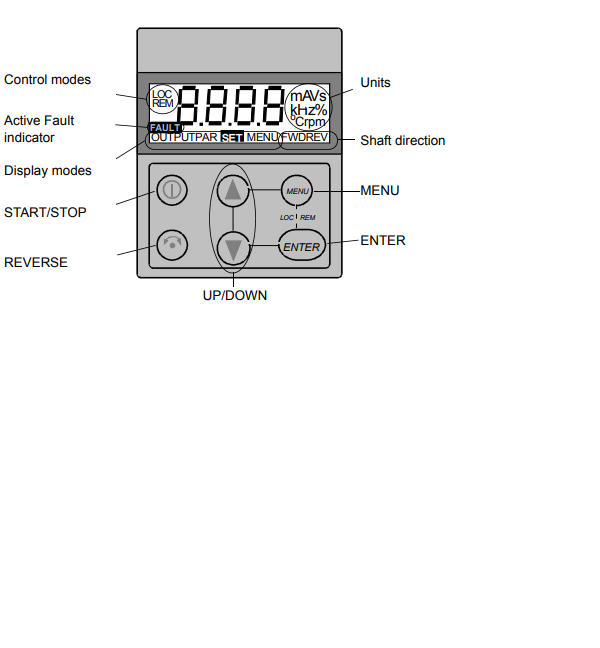
Last post by zigmund - February 18, 2024, 04:58:AMThe ABB ACS160 is a reliable drive but even reliable drives are prone to faults and occasional alarms. The seven-segment display of the control panel indicates alarms and faults using codes "ALxx"
or "FLxx", where xx is the corresponding alarm or fault code. Errors are part of life with any brand and ABB keeps the display simple.
As a couple quick notes, the alarm and fault messages disappear when MENU, ENTER or the arrow buttons of control panel are pressed. The message will reappear after a few seconds if the keypad is not touched and the alarm or fault is still active.
Also the last three fault codes are stored into parameters 0128 to 0130. These faults can be cleared from the control panel by pressing UP and DOWN buttons at the same time in parameter set mode or through serial communication mode by writing 0 into them.
The faults can be reset either from the control panel (by pressing START/STOP button), by digital input (Parameter 1604) or serial communication, or switching the supply voltage off for a while. When the fault has been removed, the motor can be started. The ACS160 can be configured to automatically reset certain faults. This would be done in parameter group 31.
AUTOMATIC RESET. OK Here is the list of codes:
LIST OF ACS160 ALARMS
Pay attention to Notes!
Alarms (*) will not cause relay output RO1 (RO2) to activate when the relay output is configured to indicate alarm condition in general. (Parameter 1401 RELAY OUTPUT 1 (1402 RELAY OUTPUT 2) has value 5 (ALARM) or 13 (FLT/ALARM)).
Note! Alarms (**) will be shown only if parameter 1608 DISPLAY ALARMS is set to 1 (YES)
LIST OF ACS160 FAULTS
or "FLxx", where xx is the corresponding alarm or fault code. Errors are part of life with any brand and ABB keeps the display simple.
As a couple quick notes, the alarm and fault messages disappear when MENU, ENTER or the arrow buttons of control panel are pressed. The message will reappear after a few seconds if the keypad is not touched and the alarm or fault is still active.
Also the last three fault codes are stored into parameters 0128 to 0130. These faults can be cleared from the control panel by pressing UP and DOWN buttons at the same time in parameter set mode or through serial communication mode by writing 0 into them.
The faults can be reset either from the control panel (by pressing START/STOP button), by digital input (Parameter 1604) or serial communication, or switching the supply voltage off for a while. When the fault has been removed, the motor can be started. The ACS160 can be configured to automatically reset certain faults. This would be done in parameter group 31.
AUTOMATIC RESET. OK Here is the list of codes:
LIST OF ACS160 ALARMS
- 1 * OPERATION FAILED Parameter upload or download failed. The software versions of the drives may not be compatible. Software version can be seen from parameter 3301 SOFTWARE VERSION.
- 2 * START ACTIVE Control panel function is not allowed while start is active.
- 3 * LOCAL/REMOTE Control panel function is not allowed in current control mode (local or remote). Control mode is local when LOC is displayed and remote mode when REM is displayed on the control panel.
- 5 * BUTTON DISABLED Control panel function is denied for any of the following reasons: • START/STOP button is interlocked from digital input. This can happen with certain digital input configurations. Refer to section on Application Macros. • REVERSE button is locked because shaft direction is fixed by parameter 1003 DIRECTION. • The drive is in remote control mode and START/STOP and REVERSE buttons are not followed.
- 6 * PARAM/LOCAL LOCK Control panel function is not allowed: • Parameter 1602 PARAMETER LOCK denies parameter editing • Parameter 1605 LOCAL LOCK denies local control mode.
- 7 * FACTORY MACRO Control panel function is not allowed: Factory macro is selected and denies the parameter modifications. Factory macro is intended for applications where there is no control panel available.
- 10 ** OVERCURRENT Overcurrent controller is active.
- 11 ** OVERVOLTAGE Overvoltage controller is active.
- 12 ** DC UNDERVOLTAGE Undervoltage controller is active.
- 13 DIRECTION LOCK Rotation direction if fixed by parameter 1003 DIRECTION.
- 14 SERIAL COMM LOSS Serial communication through Standard Modbus Channel is lost. • Check connections between external control system and the ACS160. • Refer to parameters 5204 COMM FAULT TIME and 5205 COMM FAULT FUNC.
- 15 *, ** MODBUS EXCEPTION Exception response is sent through Standard Modbus channel. The bus master may be sending queries which cannot be processed by the ACS160. Last three exception response codes are stored into parameters 5213 - 5215.
- 16 AI1 LOSS Analogue input 1 loss. Analogue input 1 value is less than MINIMUM AI1 (1301). See also parameter 3001 AI<MIN FUNCTION.
- 17 AI2 LOSS Analogue input 2 loss. Analogue input 2 value is less than MINIMUM AI2 (1306). See also parameter 3001 AI<MIN FUNCTION.
- 18 PANEL LOSS Panel communication loss. Control panel is disconnected when - Drive is in local control mode (LOC is shown in the control panel display), or - Drive is in remote control mode (REM) and is parameterized to accept start/stop, direction or reference from the panel. Refer to parameters in groups 10 COMMAND INPUTS and 11 REFERENCE SELECT. See also parameter 3002 PANEL LOSS.
- 19 ** ACS160 OVERTEMP ACS 160 overtemperature condition. This alarm is given when the temperature reaches 95% of the trip limit.
- 20 MOTOR OVERTEMP Motor overtemperature condition as estimated by the ACS 160. Refer to parameters 3004 – 3008.
- 21 UNDERLOAD Motor load is too low. Check for a problem in the driven equipment. Refer to parameters 3013 – 3015.
- 22 MOTOR STALL Motor is operating in the stall region. This may be caused by excessive load or insufficient motor power. Refer to parameters 3009 – 3012.
- 23 Reserved.
- 24 Reserved.
- 25 Reserved.
- 26 ** OUTPUT OVERLOAD Inverter overload condition. The ACS 160 output current exceeds the ratings given in Reference Section P.
- 27 * AUTOMATIC RESET ACS 160 is about to perform automatic fault reset operation. As a result, the drive may start after the reset operation. Refer to parameter group 31 AUTOMATIC RESET.
- 28 * PID SLEEP PID sleep function is active. The drive may accelerate when PID sleep function is deactivated. Refer to parameters 4018 SLEEP SELECTION, 4013 PID SLEEP DELAY, 4014 PID SLEEP LEVEL nd 4015 WAKE-UP LEVEL.
- 29 Reserved.
- 30 Reserved.
- 31 BR RES OVERLOAD Brake resistor is nearly overloaded. Refer to brake resistor instructions.
Pay attention to Notes!
Alarms (*) will not cause relay output RO1 (RO2) to activate when the relay output is configured to indicate alarm condition in general. (Parameter 1401 RELAY OUTPUT 1 (1402 RELAY OUTPUT 2) has value 5 (ALARM) or 13 (FLT/ALARM)).
Note! Alarms (**) will be shown only if parameter 1608 DISPLAY ALARMS is set to 1 (YES)
LIST OF ACS160 FAULTS
- OVERCURRENT Output current is excessive. • Motor load may be too high • Acceleration time may be too short (parameters 2201 ACCELER TIME 1 and 2203 ACCELER TIME 2). • Motor or motor cable is faulty or connected wrong.
- 2 DC OVERVOLTAGE Intermediate circuit DC voltage is excessive. • Check mains for static or transient overvoltages • Deceleration time may be too short (parameters 2202 DECELER TIME 1 and 2204 DECELER TIME 2) • Brake chopper (if present) may be underdimensioned
- 3 ACS160 OVERTEMP ACS160 heat sink temperature is excessive. Temperature trip limit is 105 degree C. • Check air flow and fan operation. • Check motor power against unit power.
- 4 ** SHORT CIRCUIT Fault current. Possible reasons for this fault are: • There is a short-circuit in the motor cable(s) or motor • Supply disturbances
- 5 OUTPUT OVERLOAD Inverter overload condition. The ACS 160 output current exceeds the ratings given in Reference Section P.
- 6 DC UNDERVOLTAGE Intermediate circuit DC voltage is not sufficient. • Mains phase may be missing • Fuse may be blown
- 7 ANALOGUE INPUT 1 Analogue input 1 loss. Analogue input value is less than MINIMUM AI1 (1301). See also parameter 3001 AI<MIN FUNCTION.
- 8 ANALOGUE INPUT 2 Analogue input 2 loss. Analogue input value is less than MINIMUM AI2 (1306). See also parameter 3001 AI<MIN FUNCTION.
- 9 MOTOR OVERTEMP Motor overtemperature condition as estimated by the ACS 160. Refer to parameters 3004 – 3008.
- 10 PANEL LOSS Panel communication loss. Control panel is disconnected when the drive is receiving start, stop and direction commands from the panel. - Drive is in local control mode (LOC is shown in the control panel display), or - Drive is in remote control mode (REM is shown) and is parameterised to accept start/stop, direction or reference from the panel. Refer to parameters in groups 10 COMMAND INPUTS and 11 REFERENCE SELECT. See also parameter 3002 PANEL LOSS.
- 11 PARAMETERING Parameter values are inconsistent: • MINIMUM AI1 > MAXIMUM AI1 (parameters 1301, 1302) • MINIMUM AI2 > MAXIMUM AI2 (parameters 1304, 1305) • MINIMUM FREQ > MAXIMUM FREQ (parameters 2007, 2008)
- 12 MOTOR STALL Motor stall. This may be caused by excessive load or insufficient motor power. Refer to parameters 3009 – 3012.
- 13 SERIAL COMM LOSS Serial communication through Standard Modbus Channel is lost. • Check connections between external control system and the ACS160. • Refer to parameters 5204 COMM FAULT TIME and 5205 COMM FAULT FUNC.
- 14 EXTERNAL FAULT SIGNAL External fault is active. See parameter 3003 EXTERNAL FAULT.
- 15 ** OUTPUT EARTH FAULT Earth fault. The load on the incoming mains system is out of balance. • There may be a fault in the motor or motor cable. • Motor cable may be too long.
- 16 ** DC BUS RIPPLE • Ripple voltages on the DC bus are too large. • Mains phase may be missing • Fuse may be blown
- 17 UNDERLOAD Motor load is too low. Check for a problem in the driven equipment. Refer to parameters 3013 – 3015.
- 18 Reserved
- 19 Reserved.
- 20 ** AI OUT OF RANGE Analogue input out of range. Check AI level.
- 21 - 29 ** HARDWARE ERROR Hardware error. Contact supplier.
- 30 BR RES OVERLOAD Brake resistor is overloaded. Refer to parameter 2005 OVERVOLT CTRL.
- 31 ENCODER FAULT Positioning macro is used, but the drive is not receiving pulses. Check the encoder and its connections. Full display blinking Serial link failure. Bad connection between the control panel and the
ACS 160.
Pay attention to Note! Faults (**) are indicated by a red blinking LED and are reset by turning the power off for a while.
Also there is plenty of other info for clearing ACS160 faults in the user manual if you have access to one.
#42
Troubleshooting 101 / ABB ACS140 Fault, Alarm, and E...
Last post by zigmund - February 10, 2024, 07:31:AMABB ACS140 Fault, Alarm, and Error Codes
Alarm and Fault Displays
Here is some good general info from their service manual. The seven-segment display unit of control panel indicates alarms and faults using codes "ALxx" or "FLxx", where xx is the corresponding alarm or fault code. Alarms 1-7 arise from button operation. Green LED blinks for AL10-21, meaning that the ACS140 cannot fully follow the control commands. The faults are indicated by red LED. The alarm and fault messages disappear by pressing MENU, ENTER or the arrow buttons of the control panel. The message will reappear after a few seconds if the keypad is not touched and the alarm or fault is still active. Last three fault codes are stored into parameters 0128-0130. These fault memories can be cleared from the control panel by pressing UP and DOWN buttons simultaneously in parameter set mode.
Fault Resetting
When the red LED of the ACS140 is on or blinking, a fault is active!!!
When the green LED of the ACS140 is blinking, an alarm is active!!!
Resetting or clearing a fault is half the battle, the other hand is clearing the error and removing the problem all together. Faults that are indicated by a red blinking LED are reset by turning the power off for a while. Other faults (indicated by red static LED) can be reset either from the control panel, by digital input or serial communication, or switching the supply voltage off for a while. When the fault has been removed, the motor can be started. The ACS140 can be configured to automatically reset certain faults. Refer to parameter group 31 AUTOMATIC RESET.
It is important to remember that if an external source for start command is selected and is still active, the ACS140 may start immediately after a fault reset.
ALARM CODE LIST
Note! The Alarms marked with an asterisk (*) will be shown only if parameter 1608 DISPLAY ALARMS is set to 1(YES) so you may not see them depending on your setting
-------------------
FAULT CODE LIST
Note! Faults marked with an asterisk (*) are indicated by a red blinking LED are reset by turning the power off and on. Other faults are reset by pressing the START/STOP button. See also parameter 1604.
I'm sure this will be a big help for anyone troubleshooting the ACS140, Good Luck!
Alarm and Fault Displays
Here is some good general info from their service manual. The seven-segment display unit of control panel indicates alarms and faults using codes "ALxx" or "FLxx", where xx is the corresponding alarm or fault code. Alarms 1-7 arise from button operation. Green LED blinks for AL10-21, meaning that the ACS140 cannot fully follow the control commands. The faults are indicated by red LED. The alarm and fault messages disappear by pressing MENU, ENTER or the arrow buttons of the control panel. The message will reappear after a few seconds if the keypad is not touched and the alarm or fault is still active. Last three fault codes are stored into parameters 0128-0130. These fault memories can be cleared from the control panel by pressing UP and DOWN buttons simultaneously in parameter set mode.
Fault Resetting
When the red LED of the ACS140 is on or blinking, a fault is active!!!
When the green LED of the ACS140 is blinking, an alarm is active!!!
Resetting or clearing a fault is half the battle, the other hand is clearing the error and removing the problem all together. Faults that are indicated by a red blinking LED are reset by turning the power off for a while. Other faults (indicated by red static LED) can be reset either from the control panel, by digital input or serial communication, or switching the supply voltage off for a while. When the fault has been removed, the motor can be started. The ACS140 can be configured to automatically reset certain faults. Refer to parameter group 31 AUTOMATIC RESET.
It is important to remember that if an external source for start command is selected and is still active, the ACS140 may start immediately after a fault reset.
ALARM CODE LIST
- AL 1 Parameter upload/download failed.
- AL 2 Operation not allowed while start is active.
- AL 3 Operation not allowed in current control mode (Local or Remote).
- AL 5 Start/Stop/Direction or reference from control panel is not followed. Possible causes: ï Remote mode: parameters disable the buttons (See APPENDIX.) ï Local mode: START/STOP button interlocked from digital inputs.
- AL 6 Operation not allowed. Parameter 1602 PARAMETER LOCK is active.
- AL 7 Use of factory macro disables operation.
- AL10* Overcurrent controller active.
- AL11* Overvoltage controller active.
- AL12* Undervoltage controller active.
- AL13 Direction lock. See parameter 1003 DIRECTION.
- AL14 Serial communication loss alarm, see ACS140 RS485 and RS232 Adapter Installation and Start-up Guide.
- AL15* Modbus exception response is sent through serial communication.
- AL16 Analogue input 1 loss. Analogue input 1 value is less than MINIMUM AI1 (1301). See also parameters 3001 AI<MIN FUNCTION and 3013 AI1 FAULT LIMIT.
- AL17 Analogue input 2 loss. Analogue input 2 value is less than MINIMUM AI2 (1306). See also parameters 3001 AI<MIN FUNCTION and 3014 AI2 FAULT LIMIT.
- AL18* Panel loss. Panel is disconnected when Start/Stop/Dir or reference is coming from panel. See parameter 3002 PANEL LOSS and APPENDIX of manual.
- AL19* Hardware overtemperature (at 95 % of the trip limit).
- AL20* Motor overtemperature (at 95 % of the trip limit), see 3004 MOTOR THERM PROT.
- AL21 Motor stall alarm. See parameter 3009 STALL FUNCTION.
Note! The Alarms marked with an asterisk (*) will be shown only if parameter 1608 DISPLAY ALARMS is set to 1(YES) so you may not see them depending on your setting
-------------------
FAULT CODE LIST
- FL 1 Overcurrent: ï Possible mechanical problem. Check for: Acceleration and/or deceleration times may be too short. OR Supply disturbances.
- FL 2 DC overvoltage: Check for: Input voltage too high. OR Deceleration time may be too short.
- FL 3 ACS140 overtemperature: Check for Ambient temperature too high. OR Severe overload.
- FL 4 * Fault current: Check for: Output earth fault (200 V units). OR Short circuit. OR Supply disturbances.
- FL 5 Output overload.
- FL 6 DC undervoltage.
- FL 7 Analogue input 1 fault. Analogue input 1 value is less than MINIMUM AI1 (1301). See also parameters 3001 AI<MIN FUNCTION and 3013 AI1 FAULT LIMIT.
- FL 8 Analogue input 2 fault. Analogue input 2 value is less than MINIMUM AI2 (1304). See also parameters 3001 AI<MIN FUNCTION and 3014 AI2 FAULT LIMIT.
- FL 9 Motor overtemperature. See parameters 3004-3008.
- FL10 Panel loss. Panel is disconnected when Start/Stop/Dir or reference is coming from panel. See parameter 3002 PANEL LOSS and APPENDIX in manual. Note! If FL10 is active when the power is turned off, the ACS140 will start in remote control (REM) when the power is turned back on.
- FL11 Parameters inconsistent. Possible fault situations: Check for MINIMUM AI1 > MAXIMUM AI1 (parameters 1301 and 1302) OR MINIMUM AI2 > MAXIMUM AI2 (parameters 1304 and 1305) OR MINIMUM FREQ > MAXIMUM FREQ (parameters 2007 and 2008)
- FL12 Motor stall. See parameter 3009 STALL FUNCTION.
- FL13 Serial communication loss.
- FL14 External fault is active. See parameter 3003 EXTERNAL FAULT.
- FL15 Output earth fault (400 V units).
- FL16 * DC bus ripple too large. Check supply.
- FL17 Analogue input out of range. Check AI level.
- FL18 - FL22 * Hardware error. Contact supplier.
- Full display blinking Serial link failure. Bad connection between the control panel and the ACS140. Check if the Serial communication parameters (group 52) have been altered. Keep panel connected and switch power off and then on again.
Note! Faults marked with an asterisk (*) are indicated by a red blinking LED are reset by turning the power off and on. Other faults are reset by pressing the START/STOP button. See also parameter 1604.
I'm sure this will be a big help for anyone troubleshooting the ACS140, Good Luck!
#43
Troubleshooting 101 / ABB ACS100 Fault Alarm and Err...
Last post by zigmund - February 10, 2024, 04:30:AMABB ACS100 Fault Codes and Alarm Help
From the ABB service manual I compiled a list of the ACS100 Fault codes or ACS100 Alarm codes, ACS100 Error codes, or whatever you like to call them. There's a lot of good information here regarding problem solving and clearing alarms on the ACS100. This list or errors will help you solve problems fast.
Alarm and Fault displays: The seven-segment display unit of control panel indicates alarms and faults using codes "ALxx" or "FLxx", where xx is the corresponding alarm or fault code. Alarms 1-6 arise from button operation.
Green LED blinks for AL10-16, meaning that the ACS 100 cannot fully follow the control commands. The faults are indicated by red LED.
The alarm and fault messages disappear by pressing MENU, ENTER or the arrow buttons of the control panel. The message will reappear after a few seconds if the keypad is not touched and the alarm or fault is still active. Last fault code is stored into parameter 102. This fault memory can be cleared from the control panel by pressing UP and DOWN buttons simultaneously in parameter set mode.
Resetting Faults (or alarms):
Faults that are indicated by a red blinking LED are reset by turning the power off for a while. Other faults (indicated by red static LED) can be reset either from the control panel, by digital input, or switching the supply voltage off for a while. When the fault has been removed, the motor can be started. The ACS100 can be configured to automatically reset certain faults. (This would be done with parameter 505 AUTO RESET which I don't cover here)
OK with that being said, here are the ACS100 faults/alarms to hopefully give you ACS100 troubleshooting help:
ACS100 ALARM CODE LIST
ACS100 FAULT CODE LIST
Please Note that Faults (*) with red blinking LED are reset by turning the power off and on. The other faults are reset by pressing the START/STOP button. And here's the fault codes:
From the ABB service manual I compiled a list of the ACS100 Fault codes or ACS100 Alarm codes, ACS100 Error codes, or whatever you like to call them. There's a lot of good information here regarding problem solving and clearing alarms on the ACS100. This list or errors will help you solve problems fast.
Alarm and Fault displays: The seven-segment display unit of control panel indicates alarms and faults using codes "ALxx" or "FLxx", where xx is the corresponding alarm or fault code. Alarms 1-6 arise from button operation.
Green LED blinks for AL10-16, meaning that the ACS 100 cannot fully follow the control commands. The faults are indicated by red LED.
The alarm and fault messages disappear by pressing MENU, ENTER or the arrow buttons of the control panel. The message will reappear after a few seconds if the keypad is not touched and the alarm or fault is still active. Last fault code is stored into parameter 102. This fault memory can be cleared from the control panel by pressing UP and DOWN buttons simultaneously in parameter set mode.
Resetting Faults (or alarms):
Faults that are indicated by a red blinking LED are reset by turning the power off for a while. Other faults (indicated by red static LED) can be reset either from the control panel, by digital input, or switching the supply voltage off for a while. When the fault has been removed, the motor can be started. The ACS100 can be configured to automatically reset certain faults. (This would be done with parameter 505 AUTO RESET which I don't cover here)
OK with that being said, here are the ACS100 faults/alarms to hopefully give you ACS100 troubleshooting help:
ACS100 ALARM CODE LIST
- CF 0 Position of configuration switch S1. Certain parameters can be modified only when S1 = 0.
- CF 1 Position of configuration switch S1. Certain parameters can be modified only when S1 = 0.
- CF 2 Position of configuration switch S1. Certain parameters can be modified only when S1 = 0.
- CF 3 Position of configuration switch S1. Certain parameters can be modified only when S1 = 0.
- CF 4 Position of configuration switch S1. Certain parameters can be modified only when S1 = 0.
- CF 5 Position of configuration switch S1. Certain parameters can be modified only when S1 = 0.
- CF 6 Position of configuration switch S1. Certain parameters can be modified only when S1 = 0.
- CF 7 Position of configuration switch S1. Certain parameters can be modified only when S1 = 0.
- CF 8 Position of configuration switch S1. Certain parameters can be modified only when S1 = 0.
- CF 9 Position of configuration switch S1. Certain parameters can be modified only when S1 = 0.
- AL 1 Parameter upload/download failed.
- AL 2 Operation not allowed while start is active.
- AL 3 Operation not allowed in remote or local control.
- AL 4 REVERSE button disabled. Parameter 208 (Dir Lock) is active.
- AL 5 Panel START button disabled.
- DI configuration is 3-wire and DI2 is open.
- AL 6 Operation not allowed. Parameter 503 (Param Lock) is active.
- AL10* Overcurrent controller active. Only shown only if parameter 506 is set to 1 (Yes).
- AL11* Overvoltage controller active.Only shown only if parameter 506 is set to 1 (Yes).
- AL12* Undervoltage controller active. Only shown only if parameter 506 is set to 1 (Yes).
- AL13 Reserved. Contact supplier.
- AL14 Reverse command attempted in remote control (REM), while parameter 208 (Dir Lock) is active.
- AL15 Reserved. Contact ABB Motor supplier.
- AL16 Reserved. Contact ABB Motor supplier.
ACS100 FAULT CODE LIST
Please Note that Faults (*) with red blinking LED are reset by turning the power off and on. The other faults are reset by pressing the START/STOP button. And here's the fault codes:
- FL 1 Overcurrent: Possible mechanical problem or Acc and/or Dec times may be too small.
- FL 2 DC overvoltage: Input voltage too high or Dec time may be too small.
- FL 3 ACS 100 overtemperature: Ambient temperature too high or Severe overload.
- FL 4 * Fault current: output earth fault or short circuit.
- FL 5 Output overload.
- FL 6 DC undervoltage.
- FL 7 Analogue input fault. (See parameter 501.)
- FL 8 Motor overtemperature. (See parameter 502.)
- FL 9 Panel disconnected from drive in local control. Note! If FL 9 is active when the power is turned off, the ACS100 will start in remote control (REM) when the power is turned back on.
- FL10 Parameters inconsistent. Check that AI min (fmin) is not greater than AI max (fmax).
- FL11 * DC bus ripple too large. Check supply.
- FL12 Reserved. Contact ABB motor/drive supplier.
- FL13 * Hardware error. Contact ABB motor/drive supplier.
- FL14 * Hardware error. Contact ABB motor/drive supplier.
- FL15 * Analogue input out of range. Check AI level.
- FL16 * Hardware error. Contact ABB motor/drive supplier.
- FL17 * Hardware error. Contact ABB motor/drive supplier.
- FL18 * Hardware error. Contact ABB motor/drive supplier.
- FL19 * Hardware error. Contact ABB motor/drive supplier.
- Full display blinking - Serial link failure or Bad connection between the control panel and the ACS100.
#44
Troubleshooting 101 / Re: ABB ACS50 Faults, Errors,...
Last post by zigmund - January 30, 2024, 04:03:AMI believe the troubleshooting guide pertains to all these models:
- ACS50-01N-01A4-1
- ACS50-01N-02A2-1
- ACS50-01N-01A4-2
- ACS50-01N-02A2-2
- ACS50-01N-04A3-2
- ACS50-01N-07A6-2
- ACS50-01N-09A8-2
- ACS50-01E-01A4-1
- ACS50-01E-02A2-1
- ACS50-01E-01A4-2
- ACS50-01E-02A2-2
- ACS50-01E-04A3-2
- ACS50-01E-07A6-2
- ACS50-01E-09A8-2
#45
Troubleshooting 101 / Re: ABB ACS50 Faults, Errors,...
Last post by benklassne - January 23, 2024, 04:42:AMNice job!
#46
Troubleshooting 101 / ABB ACS50 Faults, Errors, and...
Last post by zigmund - January 23, 2024, 04:16:AMABB ACS50 Faults, Errors, and Alarms
Guys here's a quick and easy guide for troubleshooting ACS50 faults, errors, alarms or whatever you want to call them. Straight from the manual, the troubleshooting guide is simple on these.
ACS50 has two status indication LEDs, visible through the front cover. If the drive detects a problem, the red LED will blink. After fixing the problem, reset by switching the start signal off. If start is off already, turn it first on and then off again. See the list below for the fault codes (= the number of LED blinks).
Remember the basics, Green LED On and Red LED off, ACS50 operates normally
Green LED On and Red LED Blinking means the protective function has been activated. The number of blinks indicates the fault code.
Green LED Blinking and Red LED Blinking means the ACS50 will reset automatically within 3 seconds. Warning! Motor starts, if the start signal is on so be aware of this. Automatic reset will function if the AUTORESET is ON. This is configured using the DIP switches.
Ok here's the possible causes and what to do:
- 1. DC overvoltage. 1) Mains voltage is too high: Check supply. 2) Deceleration ramp time is too short compared to the load. Automatic reset will function if the AUTORESET is ON
- 2. DC undervoltage. Mains voltage is too low: Check supply. Automatic reset will function if the AUTORESET is ON
- 3. Output short circuit: Switch off the power and check the motor windings and motor cable.
- 4. Output overcurrent. 1) Acceleration time is too short compared to the load inertia: Increase ACC/DEC time with potentiometer. 2)Motor and drive sizes do not match: Check motor.
- 5. Reserved
- 6. Analogue input value is less than 4 mA/2 V. (*) Note: This supervision is active if AI OFFSET is ON.
- 7. Motor overload (I2t overload): 1) Check the load, and verify that the motor size is suitable for ACS50. 2) Verify that setting of MOTOR I NOM potentiometer is correct.
- 8. Inverter overload or excessive internal temperature: 1) Load is too high or 2) drive cooling is insufficient.
- 9. Other fault. Internal error. Turn power off and on again. If problem persists replace the unit
#47
The Maintenance Saloon / Re: Modernizing the Obsolete
Last post by Cheller - January 21, 2024, 06:46:AMI'd personally like to hear from younger technicians here, engagement from young maintenance techs would light this place up. I think you can get a different perspective based on their age. The older technicians have built their experience in a whole different tech world so they see things differently.
#48
Troubleshooting 101 / Re: What is the Best Way to Te...
Last post by Cheller - January 21, 2024, 06:43:AMFinding fault in a contactor is best done when it's de-energized but I have to admit, the contactor test with power applied is interesting if it's done safely.
I would prefer to do the power-on tests with a digital multimeter, with your gloves on, of course.
I would prefer to do the power-on tests with a digital multimeter, with your gloves on, of course.
#49
Electrical and Electronic / Re: Looking for obsolete crane...
Last post by drodriquez - January 21, 2024, 06:31:AMCranes are a major safety concern, if I were you I'd just look towards upgrades and replacements when crane parts become obsolete
#50
Mechanical and More / Are Pittsburg Tools Good or Us...
Last post by drodriquez - January 21, 2024, 06:30:AMAre the cheap Pittsburg tools any good? Anybody have anything good to say about these? The general idea is that they're too cheap to be any good.