
You 'gotta be more specific than that.
- Welcome to OI Roundtable.

The Maintenance Technicians App
This section allows you to view all posts made by this member. Note that you can only see posts made in areas you currently have access to.
#2
The Maintenance Saloon / Re: Modernizing the Obsolete
January 21, 2024, 06:46:AM
I'd personally like to hear from younger technicians here, engagement from young maintenance techs would light this place up. I think you can get a different perspective based on their age. The older technicians have built their experience in a whole different tech world so they see things differently.
#3
Troubleshooting 101 / Re: What is the Best Way to Test a 3 Pole Contactor
January 21, 2024, 06:43:AM
Finding fault in a contactor is best done when it's de-energized but I have to admit, the contactor test with power applied is interesting if it's done safely.
I would prefer to do the power-on tests with a digital multimeter, with your gloves on, of course.
I would prefer to do the power-on tests with a digital multimeter, with your gloves on, of course.
#4
The Maintenance Saloon / Re: RS Logix 500 Hack the Activation
February 22, 2022, 07:47:PM
Hacking RSlogix isn't the way to go. Hacking Allen Bradley stuff isn't worth it, if you can't afford to pay up to these people you should probably look for an alternative. There are plenty of options that are budget friendly just look around.
#5
The Maintenance Saloon / Re: Modernizing the Obsolete
February 22, 2022, 07:42:PM
Good work Admino, and nice to see the board is still alive, keep up the modernizing
#6
Troubleshooting 101 / Re: Abbreviated List of Micromaster Faults
October 18, 2019, 04:51:PM
Here's a list of fault codes for Micromaster drives, not sure if it is model specific. It's the fault code, possible causes, and corrective actions.
F001 Overvoltage: Check whether supply voltage is within the limits indicated on the rating plate or Increase the ramp down time (P003) or Check whether the required braking power is within the specified limits.
F002 Overcurrent: Check whether the motor power corresponds to the inverter power or Check that the cable length limits have not been exceeded or Check motor lead and motor for short-circuits and earth faults. Also Check whether the motor parameters (P081 - P086) correspond with the motor being used. Check the stator resistance (P089). Try Increasing the ramp-up time (P002). Also Reduce the boost set in P078 and P079 and check whether the motor is obstructed or overloaded.
F003 Overload: Check whether the motor is overloaded or Increase the maximum motor frequency if a motor with high slip is used.
F005 Inverter overtemperature (internal heatsink sensor): Check that the ambient temperature is not too high or Check that the air inlet and outlet are not obstructed or Check that the integral fan is working.
F008 USS protocol timeout: Check the serial interface or Check the settings of the bus master and P091 - P093 or Check whether the timeout interval is too short (P093).
F010 Initialization fault / Parameter loss: * Check the entire parameter set. Set P009 to `0000' before powering down.
F011 Internal interface fault: * Switch off power and switch on again to clear.
F012 External trip (PTC): Check if motor is overloaded.
F013 Programme fault: * Switch off power and switch on again.
F030 PROFIBUS link failure: Check the integrity of the link.
F031 Option module to link failure: Check the integrity of the link.
F033 PROFIBUS Configuration error: Check the PROFIBUS configuration.
F036 PROFIBUS module watchdog: trip Replace PROFIBUS module
F074 Motor overtemperature by I2t calculation: Trip occurs only if P074 = 4, 5, 6 or 7. Check that the motor current does not exceed the value set in P083 and P086.
F075 Over current during ramping down: Increase the ramp down time (P003).
F101 Internal interface fault: * Switch off power and switch on again.
F105 Inverter overtemperature (internal sensor): Check that the ambient temperature is not too high or Check that the air inlet and outlet are not obstructed or Check that the inverter's integral fan is working
F106 Parameter fault P006: Parameter is fixed frequency(ies) and/or motor potentiometer on the digital inputs.
F112 Parameter fault P012/P013: Set parameter P012 < P013.
F151 Digital input parameter fault: Check the settings of digital input P051 to P053.
F152 Digital input parameter fault: Check the settings of digital inputs P051 to P053.
F153 Digital input parameter fault: Check the settings of digital inputs P051 to P053.
F201 P006 = 1 while P201 = 2: Change parameter P006 and/or P201.
F212 Parameter fault P211/P212: Set parameter P211 < P212.
F231 Output current measurement imbalance: See F002
F255 Watchdog Trip: Remove prime power and re-apply
#7
Electrical and Electronic / Re: What is Sensorless Vector Control
April 26, 2019, 03:55:AMQuote from: drodriquez on February 21, 2019, 10:39:AM
What is Sensorless Vector Control? Is sensorless control somehow superior to other methods, or is it just another option based on application?
It is just a technique used in variable frequency drives to rotate the force vector in the motor without the use of a shaft position sensor (any kind of angular position reporting).
The benefits include an increase in torque at the lowest speed and also the cost savings from the lack of a shaft position sensor.
#8
The Maintenance Saloon / Re: What is NEMA?
March 25, 2019, 04:36:AM
It stands for The National Electric Manufacturer's Association. NEMA Codes are a published series of
device ratings standards.
Industry uses these to evaluate or compare the performance of devices made by various manufacturers to a known standard. NEMA ratings are critical in new installations.
device ratings standards.
Industry uses these to evaluate or compare the performance of devices made by various manufacturers to a known standard. NEMA ratings are critical in new installations.
#9
Troubleshooting 101 / Re: Isolation Transformer on a Drive or Inverter
March 25, 2019, 04:35:AM
It's just a transformer with a 1 to 1 voltage ratio that provides electrical isolation between the primary and secondary windings with no alteration of voltage. These are typically used on the power input side of the drive or device to be protected.
An isolation transformer can protect the drive from a ground fault or other malfunction of nearby equipment, as well as attenuate ugly harmonics and transients on the input power.
I don't add them by default and could be wrong. I've had issues in the past where I bought an optional isolation transformer kit and added it after the fact and it actually didn't even fix my problem.
So from personal experience, I usually don't add them but I think they would be beneficial to some who are in extremely noisy environments.
#10
The Maintenance Saloon / Re: Advantage of Single Phase Power Over Three Phase
January 31, 2019, 04:29:AMQuote from: drodriquez on January 20, 2019, 06:32:AM
Is there any advantage of using single phase power over three phase power?
The biggest advantage of single phase power over three phase power is lower cost which is a direct result of less copper wire. The initial installation and cost of maintenance are lower.
#11
Troubleshooting 101 / Re: Baldor BC138 / BC139 Drive Problems
May 16, 2018, 04:31:AM
Go back to basics, is there a fuse on the output of the drive. If I'm not mistaken, these are the drives used on fractional motors with a DC output. I would say it's most likely there is an output fuse. heck the fuse and check for output voltage.
These simple checks will give you some answers.
These simple checks will give you some answers.
#12
The Maintenance Saloon / Re: What is a Schmidt Trigger?
February 07, 2018, 04:20:AMQuote from: zigmund on February 07, 2018, 04:09:AM
What is a Schmidt Trigger?
A Schmidt trigger is a squaring circuit where its output is always a square wave regardless of the shape of the input signal (or input waveform). Schmidt triggers are very useful when converting an imperfect analog signal over to a digital 1 or 0.
I think it is actually spelled something like Schmit or Schmitt.
#13
Troubleshooting 101 / Re: Weg F0150 Fault Alarm
October 23, 2017, 08:34:PM
I forgot to ask, what model or series inverter was this?
#14
Troubleshooting 101 / Re: Weg F0150 Fault Alarm
October 23, 2017, 07:06:PM
The F0150 Alarm is an overspeed fault. If you are only getting the fault occasionally, maybe it related to the loading of the motor and not necessarily the Weg inverter. You will have to look at the big picture.
#15
Troubleshooting 101 / Re: Need Source For Schematics
October 01, 2017, 06:31:PM
Sorry for the late response, but it sounds like you've already done your homework on this. I'm not aware of anyone who can supply board schematics if ISB isn't willing to. Used parts, if you can ever find them, are likely the answer there.
#16
Troubleshooting 101 / Re: Older mushroom style switch
October 01, 2017, 06:28:PM
I would say you're going to have to bite the bullet on the replacement operators (caps) or replace the entire unit with another 30mm switch. There are cheaper 30mm switches available if you'd rather change out the whole unit. If you look in the Allen Bradley Catalog you can find the part number for the operators by themselves. Then google or eBay that specific part number...
In my experience, the 30mm Allen Bradley switches are as good as they get. If it were me, I would buy the replacement operator. I'm assuming you just need the plastic colored portion of the switch.
In my experience, the 30mm Allen Bradley switches are as good as they get. If it were me, I would buy the replacement operator. I'm assuming you just need the plastic colored portion of the switch.
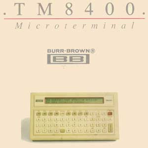
#17
Electrical and Electronic / Re: Anyone Ever Use a Burr Brown TM8400
May 29, 2017, 05:50:AM
I remember the Burr Brown keypads. I don't have any around now but can recall seeing them on more than one machine. The only thing that comes to mind with Burr Brown keypads is sticky keys...
#18
Troubleshooting 101 / Re: Troubleshooting an Old Arc Welder
February 01, 2017, 04:19:AM
Always start with troubleshooting basics. Since you didn't go into detail, check continuity of the cables, the ground and the actual arc lead first. I would make sure that nothing simple is overlooked like the ground termination or the connection in the handle. Once you have verified that these are good, you can move up to the terminals on the output of the welder and check voltage output. I would think the voltage should be marked.
#19
Troubleshooting 101 / Re: Troubleshooting an Old Arc Welder
January 29, 2017, 06:36:AMQuote from: treqilio on January 29, 2017, 05:53:AM
I am troubleshooting an old arc welder that won't arc! I'm not even sure where to begin the troubleshooting process. There is power going in, I have verified it.
What kind of old welder is it? What are the symptoms? It just doesn't weld?
#20
The Maintenance Saloon / Re: Cheap Electrical Screwdrivers
January 25, 2017, 04:00:AM
Did you price all these screwdriver sets? Is there that big of a difference? It seems like the Klein, Bondhus, and Wiha screwdrivers would all come in at about the same price. I would steer clear of cheap insulated screwdrivers just for the sake of steering clear.
#21
Troubleshooting 101 / Re: What does MISSING PULSE mean?
September 30, 2016, 09:15:AM
A Missing Pulse alarm sounds like a fault with an encoder or some type of feedback problem but I don't think that is the case with this one. View the post with the complete list of Parker drive Alarms for DC drives, not sure if that alarm list pertains to your problem. Anyway, here is what it says for the Missing Pulse alarm. As you can see, there are quite a few causes for this alarm:
MISSING PULSE (This alarm is caused by a missing pulse from the 6-pulse armature current waveform. It trips when the motor loading exceeds 1.5 times the DISCONTINUOUS parameter value. Ripple from the speed loop from either the setpoint or feedback can cause unstable current.)
Possible Reason: Drive not Autotuned (unstable current loop) Corrective Actions: Perform the AUTOTUNE procedure
Possible Reason: SCR gate connection loose Corrective Actions: Check SCR gate connections from the trigger board to the SCR gate leads
Possible Reason: SCR defective Corrective Actions: Check SCRs with an ohmmeter.
Possible Reason: SCR firing pcb defective Corrective Actions: Replace the pcb
Possible Reason: Motor has opened or shorted coil Corrective Actions: Check the motor with an ohmmeter and megger for insulation and continuity
Possible Reason: Coupling between motor and feedback device slipping Corrective Actions: Stop drive and isolate power - check coupling tightness
Possible Reason: Feedback device noisy or defective Corrective Actions: Replace tachometer generator if noise is present while observing feedback with an oscilloscope
Possible Reason: Bottom two LEDs on the 5701 Microtech receiver board are out Corrective Actions: Weak feedback signal intensity; check connections, fiber optic wire integrity, and transmission distances
Possible Reason: Speed loop gain too high Corrective Actions: Retune drive speed loop
#22
Electrical and Electronic / Re: PLC Input Card Fuses
September 28, 2016, 02:47:PMQuote from: madchad on September 28, 2016, 09:26:AM
PLC Input Card Fuses Do they exist? Can you change a fuse on a PLC input that doesn't respond to a voltage input?
I'm unaware of any PLC input cards with replaceable fuses but it's possible that some manufacturer has produced them at some point. Maybe someone else knows of something...
#23
Electrical and Electronic / Re: FREE PLC Software
September 28, 2016, 02:45:PMQuoteRe: FREE PLC Software
Great idea for a thread, looking forward to seeing a list of free PLC software by manufacturer.
#24
Troubleshooting 101 / Re: PLC Input Not Responding
September 27, 2016, 10:12:AMQuoteI have a PLC Input that is not responding.
If you have voltage at the input and the input LED is working, then it sounds like there is an internal failure in the input card, or input side of the PLC. If it is a card, you can always replace the input card. If it is a smaller PLC without removable cards, you can probably move the limit switch wire to another input and then modify the program accordingly.
#25
Troubleshooting 101 / Re: Parker 590+ Drive Alarms
September 08, 2016, 04:14:AM
Sounds like the answer will be found in your calibration. Has the calibration been dome properly for the field current? Is it set according to the motor nameplate?
#26
Mechanical and More / Re: Do air valves cause electrical noise?
September 07, 2016, 05:02:AMQuote from: stantheman on September 03, 2016, 06:14:AM
Air Valve Noise Suppression
Add noise suppressor in parallel to your air valve to reduce or eliminate the unwanted noise. Then you can move forward and continue troubleshooting from there if the problem still persists.
I agree... If you have concerns about electrical noise, snub it out and see if the problem persists. The bounce created by an air valve can most certainly cause noise. I don't see how it could increase over time, but stranger things have happened. Eliminate it and let us know if that clears up your issue.
#27
Troubleshooting 101 / Re: Westinghouse HL-71B Linatrol
August 09, 2016, 04:14:AM
What kind of problems are you having? Be more specific and maybe someone can help here.
#28
Troubleshooting 101 / Re: Indradrive Fault and Alarm List
July 26, 2016, 04:08:PM
Wow, that's a big list! Does that mean there's a lot that can go wrong with an Indradrive? 
#29
Troubleshooting 101 / Re: Indradrive Fault and Alarm List
July 26, 2016, 04:06:AM
How about your Indramat manual? You should have a chapter on troubleshooting with a detailed list of fault codes.
#30
Troubleshooting 101 / Re: AC Tech Drive Faults
July 04, 2016, 07:24:AM
List if AC Tech Faults
This is a list of some of the AC Tech warnings and status messages. I am working on a list of faults or alarms for troubleshooting and diagnostic purposes. I'm not sure on the scope of which drives these messages applied to, but I believe they match up with many from their catalog.
Status Messages (Warnings):
- br: DC-injection brake active Cause: DC-injection brake activated Remedy: Deactivate DC-injection brake, deactivate digital input
- bF: Drive ID warning Cause: The Drive ID (P502) stored on the EPM does not match the drive model. Remedy: Verify motor data (P302. . .P306) and perform Auto Calibration
- CAL: Motor Auto-calibration active Cause: Refer to P300, P399 Remedy: Motor Auto-calibration is being performed
- cE: An EPM that contains valid data from a previous software version has been installed Cause: An attempt was made to change parameter settings Remedy: Parameter settings can only be changed after the EPM data is converted to the current version
- CL: Current Limit (P171) reached Cause: Motor overload Remedy: Icrease P1 71, Verify drive/motor are proper size for application
- dEC: Decel Override Cause: The drive has stopped decelerating to avoid tripping into HF fault
Remedy: If drive trips into HF fault: Increase P1 05, P1 26, or Install Dynamic Braking option - Err: Error Cause: Invalid data was entered, or an invalid command was attempted Remedy:
- FCL: Fast Current Limit Cause: Overload Remedy: Verify drive/motor are proper size for application
- FSt: Flying Restart Attempt after Fault Cause: P110 = 5,6 Remedy: P110 = 5,6
- OE: OEM Settings Operation warning Cause: An attempt was made to change parameter settings while the drive is operating in OEM Settings mode. Remedy: In OEM Settings mode (P199 = 1), making changes to parameters is not permitted.
- OF: OEM Defaults data warning Cause: An attempt was made to use (or reset to) the OEM default settings (P1 99 = 1 or 2) using an EPM without valid OEM data. Remedy: Install an EPM containing valid OEM Defaults data
- LC: Fault Lockout Cause: Remedy:
- PdEf: PID Deceleration Status Cause: PID setpoint has finished its ramp but the drive is still decelerating to a stop. Remedy: ??
- PId: PID Mode Active Cause: Drive has been put into PID Mode. Remedy: Refer to P200
- SLP: Sleep Mode is active Cause: Refer to P240...P242 Remedy:
- SP: Start Pending Cause: The drive has tripped into a fault and will automatically restart (P110 = 3.. .6) Remedy: To disable Auto-Restart, set P1 10 = 0...2
- SPd: PID Mode disabled. Cause: Drive has been taken out of PID Mode. Refer to P200. Remedy:
- StoP: Output frequency = 0 Hz (outputs U, V, W inhibited) Cause: Stop has been commanded from the keypad, terminal strip, or network Remedy: Apply Start command (Start Control source depends on P100)