News:

Obsolete industrial electronics forum is still alive and well, just undergoing some maintenance and more anti spam stuff, stand by for a better experience

Main Menu
Menu

Show posts

This section allows you to view all posts made by this member. Note that you can only see posts made in areas you currently have access to.

Show posts Menu

Messages - Cheller

#31
"Bad input command" seems like it should be a "bad command signal"

Definition of command signal: a voltage supplied by the controller in a motion control system that commands a precise movement of a motor within a specific time frame with the desire motion profile.

A bad command signal may indicate that the controller is issuing a command voltage that is out of range. I have to admit, I am not familiar with this error. Anyone else have some feedback on bad command signals?
#32
What does excessive gain mean?

Definition of excessive gain: In relation to a motion control system, excessive gain is the concept of generating high torque and large amounts of heat within a motor due to over-correction of a small position error.

Excessive gain can cause a motor to over-correct unnecessarily hard which is where the higher current and heat come from.

How to reduce excessive gain in a motor:

Well, your motor drive combo need to be addressed in some manner. Since most manufacturers vary on tuning techniques, you may need to adjust a pot, change a parameter, or even move a jumper to reduce excessive gain.

A properly adjusted motor will not get quite as warm. A lighter load may require less gain in your settings versus a load that is a greater strain on the motor.
#33
What does bad supervisory module mean?

A technician's definition of supervisory module: relating to a motion control system, it is a component or group of components that partially tunes a drive, in other words gets it in the ballpark.

A bad supervisory module sounds like a failed component within a drive. I don't see anything here that you could do other than replace the drive unless the parts list for the drive has a specific part number for just the supervisory module.

I don't see bad supervisory module faults as being common. Anyways, maybe someone can add to this because I'm not 100% sure I'm on the right track.
#34
What does bad servo pre-amp mean?

Here's what I know... A pre-amplifier (or preamp) as relating to ay servo system is simply an electronic amplifier that prepares a smaller electrical signal for more amplification through a series of components. Basically, it is designed to boost the signal strength so it is stable enough to survive further amplification suitable for driving a motor.

As for a bad servo pre-amp, I would think it is a failure that would require circuit board replacement at the very least, or complete drive replacement in most cases. I can't say I've seen this too often. A bad motor pre-amp could also give a generic drive fault requiring drive repair or replacement depending on the manufacturer.

If you have a servo pre-amp fault or alarm, you may just want to swap drives and take it from there.

Hope that helps...
#35
What is an "overshoot error"?

I'll give you my take on overshoot. I can't say I've seen this much but I do know what overshoot is...

Definition of Overshoot: Pertaining to a motion control system, overshoot is the deviance of actual position beyond the commanded position.

For the maintenance technician, this means that following a move, the motor has gone too far and had to back up to attain the position it needs to be in. This is typically caused by instability in the motion control system that is directly related to the motor and drive tuning.

I don't see this as a common problem in a fully operable system that was in production. It would seem to be a problem that you would encounter on startup of a new system or after the replacement of a drive or servo motor.

Sometimes overshoot error can be associated to "under-damped" tuning meaning it is not responsive enough.

On the contrary, an over-damped system would be too responsive and the motor would actually seem over-cautious as it approached its desired position. An under-damped motor would approach its desired position almost like it will worry about where it needs to be after it gets there.

Overshoot is typically addressed in the tuning of the motor and drive combo. These procedures vary tremendously among manufacturers so if you encounter an overshoot error, you'll likely need to address the response of the motor with a tuning procedure from the service manual that goes with your particular drive.


#36
If you have a no control voltage fault or alarm, common sense tells me the control voltage is absent. If you've checked your control voltage and it is present, I would say that you're looking in the wrong place, or the system requires more than one control voltage (maybe 12V, 5V, etc)

The other possibility is that the circuit, or input point, that senses the control voltage has failed and it thinks there isn't any voltage. You need to dig deeper and study the schematic.
#37
OK fire away. There's a few of us who typically respond to technical questions in a relatively short period of time.
#38
I never heard of this as a maintenance problem. What is the Renshaw model number?
#39
Electrical and Electronic / Re: Remote Pot Timers
February 28, 2016, 04:53:AM
Keep us posted on your "build your own remote pot timer" project.
#40
I bought a Zen relay starter kit from one of the big name electronics suppliers a few years ago. It came with the Zen programming program. I wasn't overly impress that I would keep buying them, but it didn't work.

The only negative thing i can remember was that the programming package was cumbersome and i think that was why I got discouraged. The relay I bought is still in use today incidentally.
#41
What is this Staco transformer used for? Maybe you can just use the rest of the circuit to determine the voltage that was being supplied?
#42
Let me guess, it's beyond repair?

Did the motor catch fire?
#43
Also agree that the ladder simulates an electrical diagram, therefore making it easier for a novice to follow. I prefer ladder logic troubleshooting to the function block scenario.
#44
Allen Bradley PLC's are maintenance friendly. Their ladder logic, in particular, is easy to follow. I am partial to PLC ladder diagrams so there others that would qualify as maintenance friendly, not far behind the Allen Bradley's.
#45
Experience tells me that there is a time and place for everything. I agree that the wick is better for most applications, but if you are removing a larger amount of solder, you can get better results with a good solder sucker. I use both.

Now that I think about it though, I probably use the solder wick about 95% of the time.
#46
Electrical and Electronic / Re: Remote Pot Timers
February 14, 2016, 04:42:AM
Design your own "remote pot timer" circuit... Use the 8 pin NCC timer you found and some relay logic to make the initiate contact. That may be your best bet if you need it quickly.
#47
Electrical and Electronic / Re: Cheapest Cube Relays
February 14, 2016, 04:40:AM
I have to admit, I don't pay much attention to price that much when it comes to cube relays. I know I have Omron, P&B, Rockwell, and Dayton in use through our shop. There are probably other brands that I can't think of.

google or bing it!


  • Cheap Omron cube relay
  • Cheap Dayton cube relay
  • Cheap P&B cube relay
  • Cheap Rockwell cube relay
#48
When you say these Joslyn Clark contacts repeatedly fail, do you mean weekly, daily, or yearly? I never heard anything specifically negative with this brand name. Maybe it is the application?
#49
I have used various brands of reflectors for photo-electric switches and they seem to work fine. As for bicycle reflectors, i have never had any reason to try them,  but if I had to guess, I would say they will work. A basic photo-reflective switch shouldn't be that picky.
#50
I have never heard of any specific advantages to AC sensors over DC, or DC sensors over AC. i think the material you are sensing and the sensing distance that are designed into your equipment is what you are after.

The way I see it, if you need 2mm of sensing distance, and your sensing a steel plate, it shouldn't matter if it is AC or DC as long as the target (or object) triggers the ouput of the sensor. If anyone else knows anything more on this, please feel free to chime in.
#51
Again, I actually went researching for E-rated fuses...

E-Rated fuses are designed for use with transformers, power centers, and sub-stations. They are essentially a time delay fuse.

The NEMA Standards for E-rated fuses are as follows: They require that fuses open within 300 seconds when exposed to an RMS value of 200-240% of the fuse's current rating. It translates to a time delay fuse that is capable of an extended period of excessive current.
#52
I have to admit, I had to do some research on this fuse question. It goes to show, you learn something every day.

R-rated fuses are typical used to protest medium voltage motors and modern motor controllers. They are designed to protect electronics that are sensitive to large short circuit currents.

There are NEMA Standards for R-rated fuses. It requires that they open within 15-35 seconds when exposed to current that is 100 X the "R" rating. That is specifically RMS current.

(To me they seem like they would classify as somewhat of a semiconductor fuse, but that's just my opinion.)
#53
Try isloating the thermocouple from ground. Get creative with some kind of insulator but still contacting the surface of the motor and see what you get.
#54
I think a thermocouple ground loop is more possible than noise. A thermocouple generates a small DC voltage as it heats up and I'm not sure how it could be a noisy signal. I'm assuming the thermocouple is grounded to the surface?
#55
Step 3.

If you are new to the electronic drive world, you will need to choose a couple brands that you are comfortable with. Let's say three industrial drive manufacturers. (For example Allen Bradley, Baldor, Toshiba) Now take your specs to each one of their websites and look for an appropriate drive to meet your needs.

All the manufactures will have some type of drive configurator on their site. If you don't like that idea, just contact your local sales rep with your motor specs, and tell him (or her) your application. They can do the leg work if you want them to. Typically they end up contacting their "drives guy" (or "drives lady") who specializes in this type of work.

#56
Step 2.

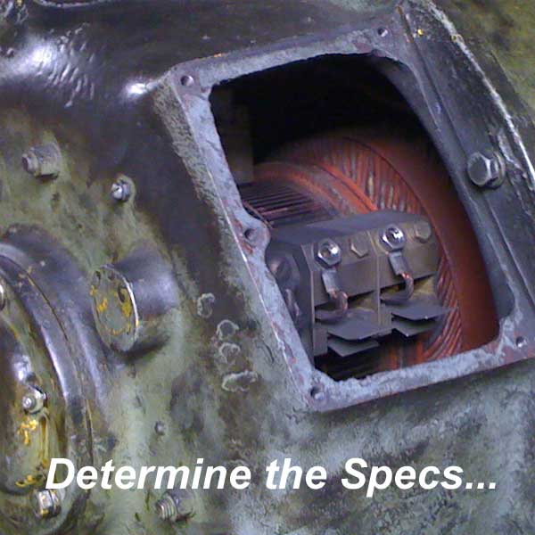
Next you'll need the specs on the DC so you can buy the appropriate drive. The motor nameplate is the key here. You'll need Armature Voltage, Armatures Current, Field Voltage, Field Currents, Horsepower, and the RPM at the bare minimum.

if the motor nameplate is not there, which seems to happen from time to time, you're most likely in trouble. you can determine both field and armature volts and current using a voltmeter, (carefully while the motor is energized). RPM would need to be determined with a handheld tachometer. Horsepower would have to be calculated based on the armature current, you could at least get a ballpark figure on the HP.


Now you're ready to buy a suitable drive....
#57
As for me being a pro, that depends who you ask...

Anyway, if I had an old DC motor that was being controlled by DC contactors, I would start by taking a step back and looking at the application first.

Do you want the motor to go both directions and have control over the speed? If you answer yes than an electronic drive is the answer.

Congratulations, that's the first step...
#58
Quote from: mallix on January 16, 2016, 04:26:AM
What is a switching power supply?


Definition of Switching Power Supply

It is just a power supply that uses a switching regulator to convert AC voltage to a DC voltage. Switching power supplies reduce and convert voltage from an AC source, to DC volts for a load.

The word "Switching" only refers to the regulator used in the voltage conversion, it has nothing to do with switching the input or output voltage to different values.

Hope that clears things up for you...
#59
Definition of Low Peak Fuse

Low Peak fuses are simply the descriptive name assigned to a line of fuses made by Bussman. I don't know of any particular meaning for the phrase.
#60
The field weakening contactor must be set in accordance with your existing motor's field current. First take not of your field current from the motor nameplate, then adjust the set screw, dial, or knob to the appropriate range.