News:

Obsolete industrial electronics forum is still alive and well, just undergoing some maintenance and more anti spam stuff, stand by for a better experience

Main Menu
Menu

Show posts

This section allows you to view all posts made by this member. Note that you can only see posts made in areas you currently have access to.

Show posts Menu

Messages - Cheller

#61
A field weakening contactor on an old DC motor starter is designed to monitor the field current and open the control circuit in the event of field current loss. The field current loss can be a result of burned or open field winding, broken wire, etc. It doesn't care, it just monitors the field current in the motor.

Field weakening contactors are more or less safety devices in the old DC contactor drives to prevent a runaway motor situation causes by the loss of the field winding.

They are adjustable because they can be used on various motors with different field currents. You will have to look at the field current rating of your existing motor to determine where to set the field weakening contactor.
#62
The service cord letters in these cable type designations are so you can determine cable characteristics. They are based on UL and the National Electrical Code. Service cord comes in many shapes and sizes.

Here's a list of the types of service cord I found on Mcmaster's website:

S—Standard cord: rated at 600V AC

SJ—Junior cord: rated at 300V AC

E—Elastomer: thermoplastic rubber coating

T—Thermoplastic coating

O—Oil Resistant insulation on the outside only

OO—Oil Resistant Inner and Outer Insulation

W—Approved for Outdoor use (not sure if it qualifies as waterproof)
#63
You need to weaken the field to exceed the base speed of the motor I'll assume. So you need to field the field weakening settings in your menu and enable it. The only other tip I could give you is that you'll need to adjust the minimum field current setting somewhere in the drive parameters. This is how you "weaken the field".

You should also consult the motor manufacturer, shoot them an email or call a rep to determine just how far you can go with the minimum field current setting. Going too far could cause flashover in the motor. It is sometimes called sparking and I'm not sure of the official explanation for flashover or sparking but I know it's bad news...

You also don't want to overspeed your bearings either so it is important to know how fast the motor can safely move.

Good luck with your field weakening.
#64
Alright, I've done some homework on this problem with battery backups producing sine waves. Some manufacturers do produce battery backups with pure sine wave outputs. This will fix your problem, they are designed for use with sensitive power supplies. That is, if you are willing to pay; since pure sine wave units are quite costly when you compare them with a battery backup that we associate with a home computer.

Next option that will work is to buy an isolation transformer that is rated to match your computer power requirements. This 150VA isolation transformer from Stancor will work:


Simply plug and play with your existing battery backup...


You can find these at Stancor distributors or on eBay.
#65
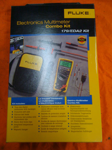
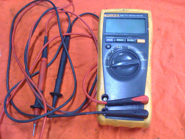
I decided to investigate True RMS meters even more, as a matter of fact I bought one....


Everything looks good and so far it works great. As for fuse testing, checking for incoming power, and other basic use, I don't anticipate seeing any difference from my older Fluke 73. I think it will come in handy when I've used it on a Freq. drive though...


The easiest and cheapest route is the check eBay.
#66
There are manuals available for download on their site, did you check there?

http://www.magnetek.com/Material%20Handling/Product%20Manuals#IMPULSE
#67
I can honestly say I have a few 1 HP AC Tech Freq drives in use and never had one go bad. Some of these are over 5 years old.

I also have a 25HP unit which I thought was no good, would have been my first AC tech drive to go south, then after some lengthy and frustrating research, I learned I had an intermittent problem with one leg of incoming power. So it was a false alarm...

Overall, I would not hesitate to buy another AC Tech.
#68
I've taken a seminar on Step 7 but never used it regularly enough to like it. It seemed like Siemens Step 7 software was easy to use immediately following the seminar, but If you aren't using it often, it feels cumbersome.

I feel like you can do some damage with Step 7 if you're not careful.
#69
I have bought a few things from Automation Direct with no problems, but never any of their PLC products. I like Allen Bradley PLC's the best. As for best value PLC's... When you look at it that way, I'm really not sure.

Allen Bradleys are nice (but they aren't cheap)

I've used a few Koyo PLC's (not by choice). These are cheaper to buy, but I have had inputs fail more than once and I never liked the software.


We need input from more members on this one...
#70
If you have the manual for the DC590 drive, is there an alarm list with troubleshooting suggestions? Missing pulse sounds like something to do with the feedback but the manual should point you in the right direction.

What are some of the suggestions for missing pulse alarm?
#71
I did a little investigating with this battery backup problem and I learned a little along the way. I unplugged a typical battery backup on my work bench and put the scope on it. I never realized the output from these battery backups were square waves but that's exactly what they are.


Here's a better look at the just the waveform on the scope:


So I grabbed a 120V isolation transformer that was way overkill for an application like a computer but I wanted to see if there was an improvement.

I had this 120V isolation transformer here:


These transformers definitely improve the quality of the signal but you still don't get that pure sine wave that you would like to see. I think this may help with a power supply being sensitive. I will do more testing, please hold...


#72
The Maintenance Saloon / Re: Stroll Down Memory Lane
November 28, 2015, 04:33:AM
Thanks for the pictures you guys. I have worked with the Electromatic timers and with the Burr Brown keypads so it's funny to see both of them.

Everyone else, keep the pictures coming. We're looking for obsolete industrial components that have come and gone throughout the years.
#73
Mechanical and More / Re: Numatic Air Valve Wiring?
November 22, 2015, 05:15:AM
Mechanic,
I know exactly what you mean. I have seen the terminal strip inside the connection box of Numatic air valves marked this way.

Basically I hung an ohmmeter on the wires and determined that the white and black wire were connected to the coil so I just disregarded the printing on the terminal block. Use an ohmmeter to double-check your valve.
#74
I'm not 100% sure on your application, but for a few bucks it would be easy enough to swap out...

http://www.ebay.com/sch/Business-Industrial-/12576/i.html?_from=R40&_nkw=MTU-004-20
#75
What is a gold-bonded relay?

As far as I know, gold bonded relays are simply relays with gold-plated contacts. Gold is used sparingly inthese so I don't think there is enough here to make them valuable.

The gold is usually applied in an alloy along with other valuable metals like silver and platinum. Gold is used in the contacts because of the electrical stability of this material. It is considered to be the least reactive metal and the yellow metal provides a low contact resistance over a long period of time.

They sometimes use gold electrical contacts for low voltage applications because they resist insulating oxide and tarnish so well. You don't see them often in standard industrial applications like motor starting and general relay logic. I think they are more of a specialized relay for low voltage circuits.
#76
I don't think you can buy the 802T contact block only for this switch. I know they have replacement part numbers for the body and operator head but nothing is listed for the contact block.

Although you can just buy a compete 802T-NPTP pretty cheap on eBay.
#77
There are boat-loads of industrial computers and industrial HMI on the market. I prefer to stick with the brand names that have been around, even if they cost more.

Allen Bradley Panel-view computers, you'll pay more but you'll feel better about the purchase.

Nematron is another good name. They have been making HMI screens for probably 30 years. I have used some of the older models but nothing recently.

GE automation most likely has industrial HMI's also, but I've never built anything with a GE industrial computer, I just know they have good solid products.

And I know if you're looking for value brands, Automation Direct has a brand called C-More. I've seen a few of these in use and they seem rugged but I can't personally vouch for them.

Those are a few suggestions that I can think of.
#78
Well... the veteran maintenance techs and electricians may be used to the old CRT style oscilloscopes, but are they better than a modern scopemeter? Which do you prefer for diagnosing electronic problems that include tricky waveforms?

Let's hear your thoughts on this one....
#79
I have some advice, and it's based on a few decades of working as a maintenance technician.

First off,  RMS means root mean square...

RMS voltage measurements are determined by converting an AC signal to DC and applying a mathematical factor to convert the reading to a numerical value. This all takes place within a true RMS meter and you just get to see the true RMS value. Their counterpart would be what is called an averaging multi-meter, which calculates an average value within the circuitry and displays that value for you to read.

Why would you need a true RMS multi-meter?

Because it can provide an accurate reading of pure sine waves as well as any complex waveforms like semi-distorted sine waves, square waves, rapid pulses, noisy signal, and even signals from switching power supplies.

Would a maintenance technician need a true RMS multi-meter?

Not if your job is limited to basic electrical tasks such as checking fuses, verifying the presence of power, testing basic switches and relays, or checking the continuity of wires. But if you go beyond fundemental electrical tests, it may be a better investment.

A true RMS multi-meter would be more often used by a maintenance technician who is exposed to diagnosing elecrical and electronic problems associated with sensors, solid state controls, variable frequency drives, motor controls and industrial motors, power supplies, low voltage systems, circuit boards,and any other equipment that may produce an unusual electrical waveform.

Although it is not a requirement, and many maintenance techs in the field still use a less costly averaging multi-meter, it may prove a better investment in the long run. In the recent past, true RMS multi-meters priced much higher than good quality averaging meters. But this gap in pricing has narrowed considerably making true RMS multi-meters more affordable than they have ever been.

If you can get more accurate readings and faster results to your troubleshooting, the return on investment is there. I personally used common averaging meters like the Fluke 27 Series or the Fluke 73/77 Series over the bulk of my maintenance career, but in hindsight, I probably should have invested in a true RMS meter some time ago.

The more research I have done, the more certain I am that my next multi-meter will be a True RMS Multi-meter.

Does anyone have anything to add?
#80
QuoteWhat is the difference between a motor megger and an insulation tester?

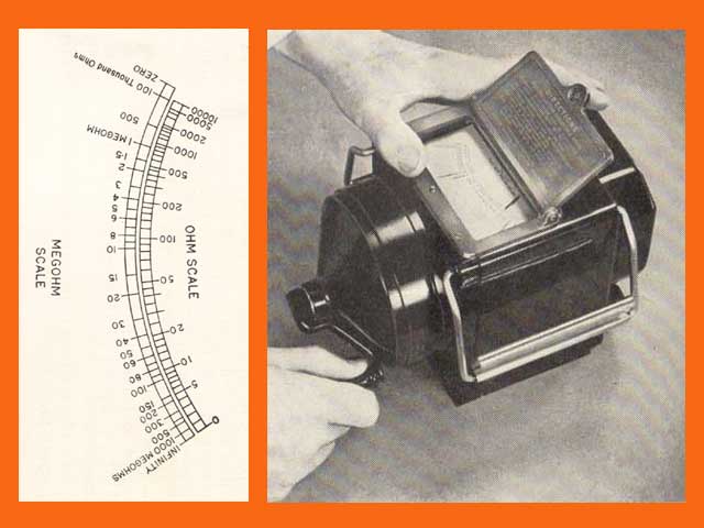
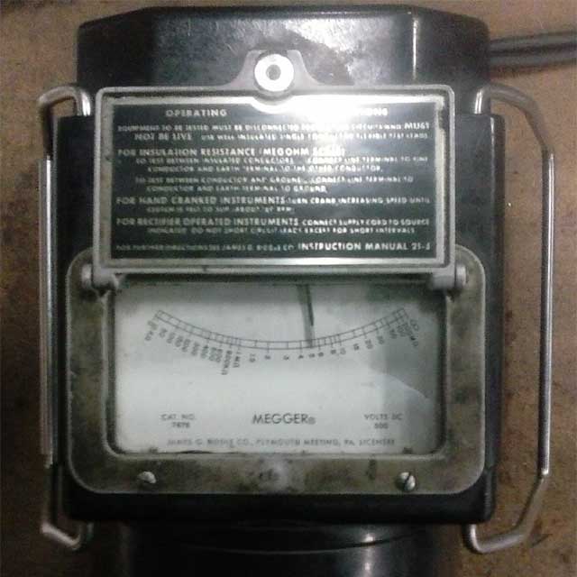
Megger is the name of the insulation tester that was manufactured by The James Biddle Company. A motor megger or just plain Megger IS an insulation tester.

Not sure when they the James Biddle Co began manufacturing Meggers, but the name caught on in the same way we typically use brand names like Band-Aid (instead of bandage).

Here's an old photo of a hand operated Megger from an operating manual:


Here's an photo of a hand operated Megger from an operating manual:


#81
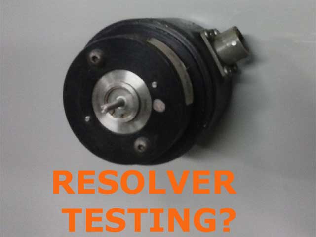
So if you're looking for the easiest way to test a resolver, I have some relatively simple suggestions, however no one line answer to the question.

First of all, the basic definition of resolver: It is an analog electrical device that is coupled to a motor. It can be physically connected externally or internally depending on the motor design. From an electrical standpoint, it is a type of rotary transformer used for measuring degrees of rotation on the motor to which it is coupled.  The most common type of resolver in industry today is the brush-less resolver.


In any event, there is actually an industry standard for the color of resolver wiring. Many, if not most manufacturers follow this standard. There are three coils in a resolver for a total of 6 wires. An excitation coil, a sine coil and a cosine coil.

Typically, red/white(+) and black/white(-) are the excitation coil. Yellow(+) and blue(-) are the sine coil, and red(+) and black(-) are the cosine coil. There are manufacturers that will use yellow/white instead of the black/white of the excitation coil. If you encounter an alternate color scheme, you may have to use an ohmmeter to determine the three coils to be sure.

As for the internal wiring of a motor resolver, it contains three individual coils. The easiest way to test a resolver is using an ohmmeter to check these coils for resistance. These can be tested with either an analog ohmmeter or a digital VOM. You should see identical resistance on the sine and cosine coils, and the excitation coil will be different.

Here is an easy test using a multimeter. Configure your meter to measure ohms for this test. This is a static test performed with the power off, of course. Check the coils individually for ohms. If any of these three coils show infinity on your ohmmeter, your resolver will need replacement. If all three coils show different resistance readings, then your resolver probably has a damaged winding and will need to be replaced or rebuilt.

In some cases, broken wiring on the connector or internal circuit board could be you only problem. A visual inspection is the key here. Get out your magnifying glass if necessary.

There are instances where external motor resolvers can also be interchanged with known working parts as a process of elimination test. Swapping identical resolvers can help identify a resolver as a failed component. It's important to remember that some resolvers may need to be zeroed, or indexed, according to the motor manufacturer's recommendations. This is accomplished using procedures an/or software provided by the manufacturer. This will depend on the application.

If you have an obsolete resolver and you're convinced you need a replacement, Check eBay for availability.

If anyone can add to these suggestions, or if you have some other resolver testing methods, that would be great...
#82
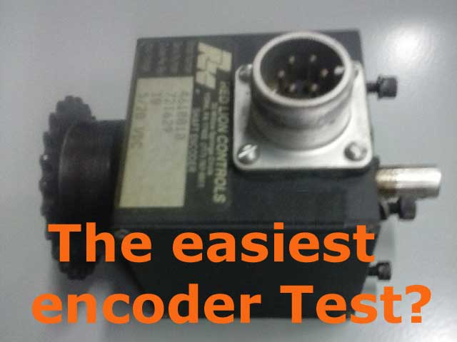
An encoder is sometimes referred to as a position encoder, a shaft encoder, or a motor encoder. Encoders come in all shapes, sizes, voltages, and pin configurations. For those trying to find out what is the easiest way to test an encoder, I have some suggestions on the matter, but not one simple test to cover all manufacturers and encoder styles.


First of all, a large percentage of encoder problems (I'm not sure of the exact figure) aren't the encoder at all. It is a cable connection between the encoder and whatever device it is providing to ( a drive, controller, PLC, etc). Broken wires and bad connections in the connector can be a nightmare, or they can be obvious. So check your cabling first.

Secondly, a mechanical connection between the encoder and the motor is a weak point that is known to fail. Either a loose set screw, broken or misaligned coupling is another source for loss of position reporting. So check the mechanical connection next.

Next you may be able to try interchanging the encoder you suspect as failed, with a known working encoder. Either off the shelf, from another point on the machine, or from another machine all together. This is a simple process of elimination and is the closest thing to the easiest way to test an encoder.

If you're the type of person who likes to have test equipment on hand. There are various encoder testers commercially available also. Check eBay for some ideas.

If anyone can add to these suggestions, that would be great...
#83
The choice of absolute encoders or incremental encoders is made when an engineer begins their project. I think it is based on the application. I'm not seeing an advantage either way, just a different way of monitoring position.

So as for an advantage of incremental versus absolute encoder, that's a grey area...
#84
I have seen charts, some posted online that depict a cross reference fuses. These are typically posted on the manufacturer websites. I don't know if I have seen anything that is primarily a semiconductor fuse cross reference however.
#85
Other than the fact that Gefran is based in Italy, I personally don't know much about them. I have been around industrial automation for as long as I can remember and haven't come across this manufacturer at all. Apparently, they are well established in the automation industry. Wish I could help you out.
#86
480V in push button and operator controls was never a good idea. OSHA or NFPA codes may dictate the use of 24V in control circuits but the grandfather situation is a good question.

24V does not ordinarily have to be guarded and covered up, so working on the controls with the box open and power on is safer than higher voltage controls.

Since the "higher authorities" like everything closed up before power is applied for 480V, it may just be better to reconfigure the control circuit to today's standards and disregard whether or not you can get away with the grandfather rule.

Higher voltage require arc-flash protection and may not be the safest thing for an operator in the event of a shorted switch or push button.
#87
I'm not aware of any standard that says reversing contactors must be interlocked mechanically and electrically, however, I think it would be good practice to wire them electrically interlocked.

I don't see the reasoning why you would want to avoid that. Better safe than sorry...
#88
Semi-conductor fuses are basically high speed fuses designed protect delicate electrical components from over-current. Using high speed semi-conductor fuses is essential since they will provide an instant reaction to a short circuit or over-current situation. They will definitely reduce the amount of component damage from short circuit current.

If you choose to skirt this fact, you will run the risk of more extensive damage during a short circuit. Manufacturers use semi-conductor fuses in these drives for a reason. Basically you would be gambling.

(I personally would wait it out.)
#89
How old is the starter? (year of manufacture) What brand is it? (Westinghouse, Allen Bradley, Cutler Hammer, etc)

I really don't see a small difference in resistance having anything to do with your problem. I believe a lower resistance in a coil will do nothing but draw more current through that particular coil. It shouldn't affect the operation of the motor starter.

These old coil operated DC motor starters are a thing of beauty. State of the art at the time and there are still some of these floating around out there.
#90
I'm gonna say, replace the board and power up. Then simply scroll through your parameters using the keypad and see if they are there. If the settings are right, you can try to start the motor.

There is a feature where you can save the parameters to the keypad on these Parker drives. Do you know if the parameters were saved there. If so, you can also load the parameters from there. I believe you would navigate to Load from Op on the menu if they were previously saved.

I have a hunch, however, that the parameters will be still there when you power back up.