
I love it when a plan comes together.... That's making more sense now.
- Welcome to OI Roundtable.

The Maintenance Technicians App
This section allows you to view all posts made by this member. Note that you can only see posts made in areas you currently have access to.
Pages1
#2
Troubleshooting 101 / Re: Recurring Power Supply Failure
February 02, 2018, 03:22:PM
It should be fused properly when you buy it. You'll find your problem once you have verified input and output voltages and currents. (or infeed and outfeed voltages and currents)
#3
Troubleshooting 101 / Re: Recurring Power Supply Failure
January 31, 2018, 03:56:AM
This shouldn't be hard to nail down, how about the incoming voltage, did you check and see if it is within spec? I'm assuming it is 120VAC. You can do this without replacing it again.
But I do think you'll need to put another power supply in place in order to do some real time monitoring. I would replace it and check incoming and outgoing voltages making sure they are accurate.
But I do think you'll need to put another power supply in place in order to do some real time monitoring. I would replace it and check incoming and outgoing voltages making sure they are accurate.
#4
Troubleshooting 101 / Re: Recurring Power Supply Failure
January 30, 2018, 04:59:AM
I'll assume you've checked the current draw on the output and the fuse you also checked for proper sizing. ?? these would be the first steps in identifying a recurring blown power supply.
#5
The Maintenance Saloon / Re: Triplett 630-NA Meter
September 11, 2017, 04:23:AM
Additional Information from the Meter Manual
How to Measuring Kilovolts
For measuring the high voltage employed in television receivers and in other applications, an external probe is available. Probes are made in three ranges, 0-12,000, 0-30,000 and 0-60,000 volts. Common usage is on DC. Probes for AC are also available in the lower ranges.
To use the D. C. Kilovolt probe set the range selector switch on the 3 volt D. C. position, and set the slide switch on the V-n-A position. When the A. C. probe is used set the range selector switch on the 3 volt A. C. position, set the slide switch on the V-OHM-A position. Plug the Kilovolt probe lead into the V-OHM-A jack at the lower right corner of the front panel. Use the black standard lead for negative or common lead with it connected into the COM jack located on the lower right side of the front panel.
The following accessories for meaasuring KV on a 630 meter are available from a Triplett meter distributor:
Hi-Voltage probe 0-30 Kv DC and 0-60 Kv AC (Part Number: T-79-152)
Hi-Voltage probe 0-30 Kv AC (Part Number: T-79-71)
USE EXTREME CAUTION in measuring the high voltages such as found in old television receivers. Clip the common lead to the circuit so you will have only one probe in your hand.
Set SelectÂor Switch Set Slide Switch
3 V DC V-OHM-A 0-300V 100
3 V AC V-OHM-A 0-300V 100
3 V AC V-OHM-A 0-60V 1000
ADDITIONAL APPLICATIONS
In The Home
When your refrigerator motor fails to "kick out" the startÂing winding, use the 630-NA to measure the AC line voltage. If the voltage is below 100 volts, notify your power company.
If your electric stove does not seem to heat quickly enough, measure the voltage input to the stove with all burners turned on and again with all burners turned off. If the difference between these two voltages is 10 or 15 volts, the power cable to the stove has defective connections or is not of large enough current carrying capacity.
Blown fuses sometimes do not visibly indicate they are burned out. With your 630-NA, measure the voltage ahead of and behind the fuse. Voltage ahead of the fuse but no voltage following indicates a blown, defective, or loose fuse. SomeÂtimes it is easier to remove the fuse and measure its resisÂtance. This should be substantially zero.
Your 630-NA is handy for locating trouble in desk and floor lamps. Pull the plug from the wall socket and check for a faulty cord, plug, switch, socket, or bulb by measuring resistance on the O-X1 range. 100 watt 120 volt bulbs should read 10 to 20 ohms. 50 watt 120 volt bulbs should read 20 to 40 ohms.
For the Radio Man
In addition to all common voltage, current, and resistance measurements used in servicing radios, the high sensitivity of your 630 meter is well adapted to measuring AFC, AVC, bias and FM discriminator voltages.
Measurements of high voltage up to 27,000 volts used in some television receivers for the picture tube can be effected with the special high voltage probe.
Considerable trouble is had with leakage in automobile radio antennas (due to moisture). Your 630 with the high ohm range 0-100 meg. is ideal to check this leakage. DisÂconnect the antenna from the receiver before making this check.
The Industrial Plant
Your 630 meter will be a big help in checking voltage drop caused by adding that extra machine on the already overloaded line. Correcting this will often save time later when a rush comes and the line "just happens" to burn up.
First measure the voltage at the machine with the machine turned off; then again with the machine in operation. If the voltage is proper with the machine off but low with the machine in operation, the circuit wiring or transformers have too small a capacity. If the voltage is low even with the machine off, the circuit is probably already overloaded and the machine should be wired into another circuit.
Equipment using automatic electric controls can be checked with the 630 meter. Faulty relay or control action is often caused by low voltage applied to the relay or control. This low voltage in turn, may be caused by burned or dirty contacts on the control device. Use the OX1 range to check for high or unstable contact resistance.
When a phone on your dial telephone system fails, measure the line current and the voltage to the particular relay in question. If the voltage is proper, measure the contact resistance of the relay contacts using the OHM Xl scale on the 630 meter. If this resistance is over a fraction of an ohm or if the resistance seems to waver, clean and adjust the relay contacts.
In The Garage
Fuses in the automobiles have a tendency to look perÂfectly good and yet not function due to corrosion under the metal end cap. Measure the voltage ahead and behind the fuse to determine a defective unit. Or remove the fuse and measure its resistance. Anything over a fraction of an ohm is too high.
Checking automobile v/iring, light switches, heaters, radios, etc., can be speeded up by simple use of the 630 meter.
In The Laboratory
Your 630 meter is built with all precision, non-aging resistors. The specially designed switch and special banana type plugs insure lasting accuracy. The meter with Taut-Band Suspension and a well designed stable magnet further makes the 630 meter a must for the laboratory.
Special Applications
The unusually high range ohmmeter in your 630-NA permits some indication of condenser leakage resistance. Measure as a resistor, see page 10, using the highest range. A good paper or mica condenser under 1 mfd. will indicate at the 100 Meg. mark or above. If a steady reading (taken after the initial surge required to charge the condenser) of less than 100 megohms is obtained, the condenser probably has defective insulation.
Good paper condensers over 1 mfd. may read somewhat less than 100 megohms. Electrolytic condensers, should read above .1 megohm. In checking electrolytic condensers, the black test lead (COM jack) should be connected to the positive terminal of the condenser.
Checks of insulation resistance for motors, generators, telephone cables, power cables, etc., can be made on the high ohmmeter range of your 630-NA. The actual value of resistance may vary from a few megohms to over 100 meg., depending on weather conditions and quality of insulation.
The best method, therefore, is to make periodic checks on important cables or equipment and observe the trend in readings. As the readings tend to be lower and lower, it is time to start drying out the equipment or determine the cause of deterioration. Dirt, mice, or foreign matter can sometimes cause excessive leakage.
Audio Specialist
The model 630 meter is the ideal instrument for audio enÂgineering and maintenance. The frequency compensation in this instrument will allow you to read volume level from 35 cycles/sec (Hz) to 20KHz.
Battery Replacement
Two batteries are used for the ohmmeter circuits, a 1.5 volt Burgess No. 2 or equivalent and a 30 volt Ever-cady No. 413 or equivalent.
When the meter pointer can no longer be adjusted to zero (see page 10) ohms on the OX1, OHMXlO, or OHMXlOOO ranges, replace the 1.5 volt battery.
When the meter pointer can no longer be adjusted to zero ohms on the OHMXlO.OOO and OHMX100,000 range, replace the 30 volt battery.
To replace batteries, remove the four screws in the bottom of the case and lift panel from the case. Remove the old battery and replace with a new one.
Fuse Replacement
A one ampere fuse is incorporated in the ohm circuits for protecting the ohm circuit when it is accidentally placed across high voltage. A spare fuse is attached to unit inside the tester. Note: This fuse is in series with ohmmeter circuit and is physically mounted on the back of the meter housing. You are cautioned not to substitute the indicated 3AG Littlefuse tor it can disturb the balance of the circuit and read in error.
Cleaning Plastic Window
The plastic window has been treated at the factory to dissipate static charges. If cleaning is required, use cotton dipped in a solution of common household detergent and water. After cleaning, allow the solution to dry without rubbing.
Care
Avoid placing your tester on a bench where machine tools are used or severe vibration is encountered. If the unit has not been in use for a long period of time, rotating the switch in both directions several times will wipe the contacts clean for good contact.
In use, don't take chances on overloading the resistors or shunts. If in doubt as to the approximate reading always start with the highest range.
Turn the selector switch to OFF when the unit is to be carried. With the selector switch in the OFF position the meter is damped and this will prevent wild swinging of the pointer.
That's about all I think is important here, there are spare parts lists and some other details but these posts pretty much encompass everything you would ever need.
#6
The Maintenance Saloon / Re: Triplett 630-NA Meter
September 10, 2017, 06:10:AM
How to Measure Capacitor with Triplett 630 Meter
Your 630 meter can be used to measure a capacitor by the arrangement shown in the image below. For such measureÂments the tester is set up as an AC voltmeter.
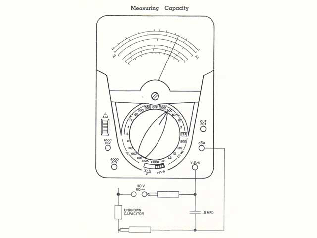
Use the following chart to determine the AC voltage range to use. ALWAYS start with the selector switch on the 300 volt range for if the condenser is shorted, serious damage may result to the meter when on a low range.
To Measure .002 Mfd, Set selector Switch to 3 AC Volts, Deflection Should Be .45 AC Volts
To Measure .004 Mfd, Set selector Switch to 3 AC Volts, Deflection Should Be .83 AC Volts
To Measure .006 Mfd, Set selector Switch to 3 AC Volts, Deflection Should Be 1.25 AC Volts
To Measure .008 Mfd, Set selector Switch to 3 AC Volts, Deflection Should Be 1.65 AC Volts
To Measure .010 Mfd, Set selector Switch to 3 AC Volts, Deflection Should Be 2.10 AC Volts
To Measure .020 Mfd, Set selector Switch to 12 AC Volts, Deflection Should Be 4.3 AC Volts
To Measure .040 Mfd, Set selector Switch to 12 AC Volts, Deflection Should Be 7.7 AC Volts
To Measure .050 Mfd, Set selector Switch to 12 AC Volts, Deflection Should Be 9.7 AC Volts
To Measure .080 Mfd, Set selector Switch to 60 AC Volts, Deflection Should Be 14.5 AC Volts
To Measure .100 Mfd, Set selector Switch to 60 AC Volts, Deflection Should Be 17.5 AC Volts
To Measure .200 Mfd, Set selector Switch to 60 AC Volts, Deflection Should Be 30.0 AC Volts
To Measure .400 Mfd, Set selector Switch to 60 AC Volts, Deflection Should Be 45.0 AC Volts
To Measure .600 Mfd, Set selector Switch to 60 AC Volts, Deflection Should Be 57.0 AC Volts
To Measure .800 Mfd, Set selector Switch to 300 AC Volts, Deflection Should Be 65 AC Volts
To Measure 1.00 Mfd, Set selector Switch to 300 AC Volts, Deflection Should Be 75 AC Volts
To Measure 2.00 Mfd, Set selector Switch to 300 AC Volts, Deflection Should Be 85 AC Volts
To Measure 5.00 Mfd, Set selector Switch to 300 AC Volts, Deflection Should Be 95 AC Volts
To Measure 10.0 Mfd, Set selector Switch to 300 AC Volts, Deflection Should Be 100 AC Volts
CAUTION: DO NOT ATTEMPT TO USE THIS TEST ON ELECTROLYTIC CONDENSERS
Your 630 meter can be used to measure a capacitor by the arrangement shown in the image below. For such measureÂments the tester is set up as an AC voltmeter.
Use the following chart to determine the AC voltage range to use. ALWAYS start with the selector switch on the 300 volt range for if the condenser is shorted, serious damage may result to the meter when on a low range.
To Measure .002 Mfd, Set selector Switch to 3 AC Volts, Deflection Should Be .45 AC Volts
To Measure .004 Mfd, Set selector Switch to 3 AC Volts, Deflection Should Be .83 AC Volts
To Measure .006 Mfd, Set selector Switch to 3 AC Volts, Deflection Should Be 1.25 AC Volts
To Measure .008 Mfd, Set selector Switch to 3 AC Volts, Deflection Should Be 1.65 AC Volts
To Measure .010 Mfd, Set selector Switch to 3 AC Volts, Deflection Should Be 2.10 AC Volts
To Measure .020 Mfd, Set selector Switch to 12 AC Volts, Deflection Should Be 4.3 AC Volts
To Measure .040 Mfd, Set selector Switch to 12 AC Volts, Deflection Should Be 7.7 AC Volts
To Measure .050 Mfd, Set selector Switch to 12 AC Volts, Deflection Should Be 9.7 AC Volts
To Measure .080 Mfd, Set selector Switch to 60 AC Volts, Deflection Should Be 14.5 AC Volts
To Measure .100 Mfd, Set selector Switch to 60 AC Volts, Deflection Should Be 17.5 AC Volts
To Measure .200 Mfd, Set selector Switch to 60 AC Volts, Deflection Should Be 30.0 AC Volts
To Measure .400 Mfd, Set selector Switch to 60 AC Volts, Deflection Should Be 45.0 AC Volts
To Measure .600 Mfd, Set selector Switch to 60 AC Volts, Deflection Should Be 57.0 AC Volts
To Measure .800 Mfd, Set selector Switch to 300 AC Volts, Deflection Should Be 65 AC Volts
To Measure 1.00 Mfd, Set selector Switch to 300 AC Volts, Deflection Should Be 75 AC Volts
To Measure 2.00 Mfd, Set selector Switch to 300 AC Volts, Deflection Should Be 85 AC Volts
To Measure 5.00 Mfd, Set selector Switch to 300 AC Volts, Deflection Should Be 95 AC Volts
To Measure 10.0 Mfd, Set selector Switch to 300 AC Volts, Deflection Should Be 100 AC Volts
CAUTION: DO NOT ATTEMPT TO USE THIS TEST ON ELECTROLYTIC CONDENSERS
#7
The Maintenance Saloon / Re: Triplett 630-NA Meter
September 10, 2017, 05:50:AM
How to Measure DB with Triplett 630 Meter
Output is generally measured in units called the decibel, a terminology used to indicate power levels in amplifiers or telephone work. The DB scale on your meter is based on the voltage developed across a 600 ohm line when .001 watts is dissipated in the line. Do not confuse the DB with the VU (Volume Unit).
Rotate the selector switch to the appropriate AC volt range, (see previous procedure for measuring AC Volts). Refer to the small chart on the meter dial for the range to use. Always start with the highest range if in doubt as to the approximate number of decibels.
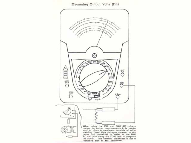
Normally it is recommended output be measured by plugging the black test lead into the "COM" jack and the red lead into the "OUTPUT" jack.
Often a DC voltage is present in the circuit where output is to be measured. The extra jack marked "OUTPUT" with a .1 mfd condenser in series is provided to block the DC.
The condenser impedance is generally disregarded in most measurements. Where no DC is present, this output voltage can be read accurately by using the 630 meter as a regular AC voltmeter (i. e. by plugging the red lead into the "V-OHM-A" jack instead of "OUTPUT").
Connect the test leads across the plate circuit or 600 ohm line.
Read all DB ranges on the bottom black scale, with the small chart on the meter dial. For example, when the selector switch is set on the 3 AC volt range and the slide switch in V-OHM-A position, the DB scale is direct reading.
When on the 12 AC volt range, add 12 to each number on the DB scale, thus with the meter reading -2, the actual DB reading is +10DB. If line impedance is not 600 ohms (as in speaker voice coils) the readings will be only relative - not actual DB.
When measuring AC volts oi high frequency such as 15,000 to 20,000 Hz, it is best to clip the leads to the voltage point under test. Hand capacity can affect the voltage reading at high frequency.
A. F. or Decibels
Audio output generally is measured in units called Decibels, a terminology used to indicate audio power levels in an amplifier to telephone work. Zero DB is set at .775 Volts, this being the voltage developed across a 600 Ohm line when .001 Watt is dissipated in the line.
DO NOT confuse the DB with the VU (Volume Unit.) The VU is based on .001 Watt dissipated in a 600 ohm line and is measured with a meter having special ballistic characteristics.
Decibels are measured by means of the Black DB Scale as indicated in the image above.
Output is generally measured in units called the decibel, a terminology used to indicate power levels in amplifiers or telephone work. The DB scale on your meter is based on the voltage developed across a 600 ohm line when .001 watts is dissipated in the line. Do not confuse the DB with the VU (Volume Unit).
Rotate the selector switch to the appropriate AC volt range, (see previous procedure for measuring AC Volts). Refer to the small chart on the meter dial for the range to use. Always start with the highest range if in doubt as to the approximate number of decibels.
Normally it is recommended output be measured by plugging the black test lead into the "COM" jack and the red lead into the "OUTPUT" jack.
Often a DC voltage is present in the circuit where output is to be measured. The extra jack marked "OUTPUT" with a .1 mfd condenser in series is provided to block the DC.
The condenser impedance is generally disregarded in most measurements. Where no DC is present, this output voltage can be read accurately by using the 630 meter as a regular AC voltmeter (i. e. by plugging the red lead into the "V-OHM-A" jack instead of "OUTPUT").
Connect the test leads across the plate circuit or 600 ohm line.
Read all DB ranges on the bottom black scale, with the small chart on the meter dial. For example, when the selector switch is set on the 3 AC volt range and the slide switch in V-OHM-A position, the DB scale is direct reading.
When on the 12 AC volt range, add 12 to each number on the DB scale, thus with the meter reading -2, the actual DB reading is +10DB. If line impedance is not 600 ohms (as in speaker voice coils) the readings will be only relative - not actual DB.
When measuring AC volts oi high frequency such as 15,000 to 20,000 Hz, it is best to clip the leads to the voltage point under test. Hand capacity can affect the voltage reading at high frequency.
A. F. or Decibels
Audio output generally is measured in units called Decibels, a terminology used to indicate audio power levels in an amplifier to telephone work. Zero DB is set at .775 Volts, this being the voltage developed across a 600 Ohm line when .001 Watt is dissipated in the line.
DO NOT confuse the DB with the VU (Volume Unit.) The VU is based on .001 Watt dissipated in a 600 ohm line and is measured with a meter having special ballistic characteristics.
Decibels are measured by means of the Black DB Scale as indicated in the image above.
#8
The Maintenance Saloon / Re: Triplett 630-NA Meter
September 10, 2017, 05:43:AM
How to Measure DC Current with Triplett 630 Meter
Rotate the selector switch to the appropriate range for DC current. Always start with the highest range if in doubt as to the approximate current. In choosing ranges, endeavor to have the readings fall in the upper, or right hand, half of the scale for greatest accuracy.
Plug the black test probe into the "COM" jack and the red probe into the V-OHM-A as shown in the image below.
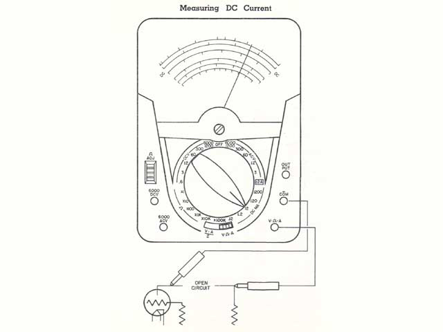
Connect the test probes in series with the circuit to be measured. Do not test directly across any potential circuits as this may burn out the shunt. The red lead is positive. Where polarity is difficult to determine, the meter may read backwards. No damage will be done if this occurs. Simply reverse the leads.
All DC current ranges are read on the scale just below the mirror.
With Slide Switch in V-n-A Position
The full scale reading of the instrument is identical to that indicated by the large range switch knob. Thus with the range switch knob at 120, note that the 0-120 Milliamperes is read on the 12 Milliampere scale simply by adding one zero (or multiply by 10). Other ranges are read similarly by adding or omitting zeros as required.
With Slide Switch In V-A/2 Position:
The instrument will read exactly half of the value indicated by the large range switch knob. Thus with the range knob set at 120 the meter actually will read 60 Milliamperes. Other ranges are handled in a similar fashion.
CAUTION: Turn oif the power before connecting the meter to the circuit. Do not handle the tester or leads in high voltage circuits.
In using the 60 microamp (uA) range, the meter reading may differ from actual calculations. This is sometimes caused in low current circuits by a slight leakage of voltage due to moisture.
Other times a slight potential is generated by soldering or joining dissimilar metals. Even the proximity of fumes or liquid acids and alkalies may react with the metal parts of the circuit and generate slight current. The fingers should not be permitted to touch the metal parts of the probes or circuit, as body resistance can also upset some circuits.
How to Measure High DC Current
External plug-in shunts are available to extend the DC current ranges of your 630 from the self-contained 0-12 amps range to 0-30 amps. External portable shunts up to 120 amps also are available.
Required Meter Accessories for High DC Current Measurements
Plug-in external shunt 0-30 DC Amp. (Part Number: T-91-429)
Portable external shunt 0-60 DC Amp. (Part Number: T-91-430)
Portable external shunt 0-120 DC Amp. (Part Number:T-91-431)
Set the 630 selector switch to the 12 mA position and plug the desired external shunt into the COM and V-OHM-A jacks.
Connect the line to be measured to the binding posts on top of the shunts. The external portable shunts are too large to plug into the panel and must be connected to the panel jacks by the leads furnished with the shunts.
Rotate the selector switch to the appropriate range for DC current. Always start with the highest range if in doubt as to the approximate current. In choosing ranges, endeavor to have the readings fall in the upper, or right hand, half of the scale for greatest accuracy.
Plug the black test probe into the "COM" jack and the red probe into the V-OHM-A as shown in the image below.
Connect the test probes in series with the circuit to be measured. Do not test directly across any potential circuits as this may burn out the shunt. The red lead is positive. Where polarity is difficult to determine, the meter may read backwards. No damage will be done if this occurs. Simply reverse the leads.
All DC current ranges are read on the scale just below the mirror.
With Slide Switch in V-n-A Position
The full scale reading of the instrument is identical to that indicated by the large range switch knob. Thus with the range switch knob at 120, note that the 0-120 Milliamperes is read on the 12 Milliampere scale simply by adding one zero (or multiply by 10). Other ranges are read similarly by adding or omitting zeros as required.
With Slide Switch In V-A/2 Position:
The instrument will read exactly half of the value indicated by the large range switch knob. Thus with the range knob set at 120 the meter actually will read 60 Milliamperes. Other ranges are handled in a similar fashion.
CAUTION: Turn oif the power before connecting the meter to the circuit. Do not handle the tester or leads in high voltage circuits.
In using the 60 microamp (uA) range, the meter reading may differ from actual calculations. This is sometimes caused in low current circuits by a slight leakage of voltage due to moisture.
Other times a slight potential is generated by soldering or joining dissimilar metals. Even the proximity of fumes or liquid acids and alkalies may react with the metal parts of the circuit and generate slight current. The fingers should not be permitted to touch the metal parts of the probes or circuit, as body resistance can also upset some circuits.
How to Measure High DC Current
External plug-in shunts are available to extend the DC current ranges of your 630 from the self-contained 0-12 amps range to 0-30 amps. External portable shunts up to 120 amps also are available.
Required Meter Accessories for High DC Current Measurements
Plug-in external shunt 0-30 DC Amp. (Part Number: T-91-429)
Portable external shunt 0-60 DC Amp. (Part Number: T-91-430)
Portable external shunt 0-120 DC Amp. (Part Number:T-91-431)
Set the 630 selector switch to the 12 mA position and plug the desired external shunt into the COM and V-OHM-A jacks.
Connect the line to be measured to the binding posts on top of the shunts. The external portable shunts are too large to plug into the panel and must be connected to the panel jacks by the leads furnished with the shunts.
#9
The Maintenance Saloon / Re: Triplett 630-NA Meter
September 10, 2017, 05:34:AM
How to Measure Resistance with Triplett 630 Meter
Rotate the selector switch to the appropriate range for ohms determined from the following chart:
To read ohms the slide switch must be in the right V-OHM-A position.
0-1,000 ohms = X1
0-10,000 ohms = X10
0-100,000 ohms = X100
0-1,000,000 ohms = X1K
fl-10,000,000 ohms = X10K
0-100,000,000 ohms = X100K
Plug the black test leads into the "COM" jack and the red lead into the V-OHM-A jack as shown in the image.
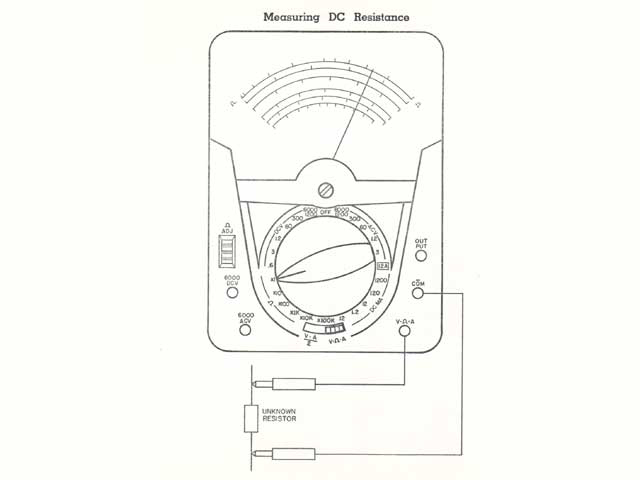
Short the test probes together and adjust the OHMS-ADJ control until the meter pointer reads 0 on top red ohms scale.
Connect the test probes across the resistor as shown. If the resistor is wired in a circuit, disconnect one end of the resistor before taking the reading. Each time an ohm range is changed, it is well to check the zero setting as outlined in paragraph above.
The basic scale 0-1K (0-1000 ohms) is used for reading all ohm ranges. Simply multiply the scale numbers by 10, 100, IK, 10K, 100K as indicated by the selector switch setting. It should be kept in mind that in the measurement of resistance a current is passed through the unknown resistor.
Generally this current is so small as to be negligible. HowÂever, on the X1 range fairly high current is employed.
CAUTION: On the X1 ohm position reading at center scale (4.4 ohms) the current drain from the 1.5 volt battery is 170 mA. It is desirable to make a practice of using one of the higher ohm ranges for general continuity or circuit the life of the batteries.
Since the scale of an ohmmeter is non-linear, the acÂcuracy of the reading cannot be expressed as a per cent of full scale. Ohmmeter accuracy is generally referred to a linear scale such as the DC volt scale. Thus +/-3% ohmmeter accuracy means an allowable +/- 1.8 division on the 60 division DC scale. For example 2 ohms could read from about 1.75 to 2.3 ohms and be within tolerance.
Rotate the selector switch to the appropriate range for ohms determined from the following chart:
To read ohms the slide switch must be in the right V-OHM-A position.
0-1,000 ohms = X1
0-10,000 ohms = X10
0-100,000 ohms = X100
0-1,000,000 ohms = X1K
fl-10,000,000 ohms = X10K
0-100,000,000 ohms = X100K
Plug the black test leads into the "COM" jack and the red lead into the V-OHM-A jack as shown in the image.
Short the test probes together and adjust the OHMS-ADJ control until the meter pointer reads 0 on top red ohms scale.
Connect the test probes across the resistor as shown. If the resistor is wired in a circuit, disconnect one end of the resistor before taking the reading. Each time an ohm range is changed, it is well to check the zero setting as outlined in paragraph above.
The basic scale 0-1K (0-1000 ohms) is used for reading all ohm ranges. Simply multiply the scale numbers by 10, 100, IK, 10K, 100K as indicated by the selector switch setting. It should be kept in mind that in the measurement of resistance a current is passed through the unknown resistor.
Generally this current is so small as to be negligible. HowÂever, on the X1 range fairly high current is employed.
CAUTION: On the X1 ohm position reading at center scale (4.4 ohms) the current drain from the 1.5 volt battery is 170 mA. It is desirable to make a practice of using one of the higher ohm ranges for general continuity or circuit the life of the batteries.
Since the scale of an ohmmeter is non-linear, the acÂcuracy of the reading cannot be expressed as a per cent of full scale. Ohmmeter accuracy is generally referred to a linear scale such as the DC volt scale. Thus +/-3% ohmmeter accuracy means an allowable +/- 1.8 division on the 60 division DC scale. For example 2 ohms could read from about 1.75 to 2.3 ohms and be within tolerance.
#10
The Maintenance Saloon / Re: Triplett 630-NA Meter
September 10, 2017, 05:21:AM
How to Measure AC Volts with Triplett 630 Meter
Rotate the selector switch to the appropriate range for AC volts. Always start with the highest range if in doubt as to the approximate voltage. In choosing ranges, endeavor to have the readings fall in the upper, or right hand, half of the scale for greatest accuracy.
Plug the black test lead into the "COM" jack and the red lead into the V-OHM-A jack as shown in the image.
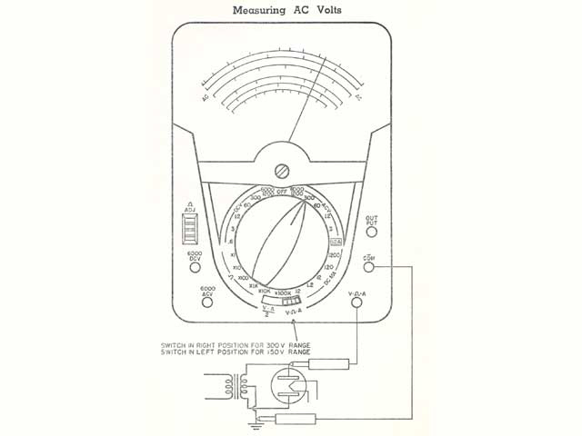
The AC range up to and including 300 volts is comÂpensated frr frequencies from 35 cycles/sec (35Hz) to 20 K cycles (20KHz). Over this range an additional 5% accuracy should be allowed, priÂmarily for the higher ranges and frequencies. The lower frequencies will exhibit negligible error.
CAUTION: When measuring up to 6000 volts, set the selector switch on the 6000/1200 range, plug the red lead into the jack marked "6000 ACV" and leave the black load in the "COM" jack.
Connect the test probes ACROSS the voltage source. As there is no polarity on AC, the red and black leads may be interchanged without causing the meter to read backwards.
All AC ranges are read on the two black center scales except 3V and 1.5V. For greater accuracy two separate red scales have been provided to read 3V-AC and 1.5V-AC.
With Slide Switch In V-OHM-A Position:
The lull scale reading of the instrument is identical to that indicated by the large range switch knob. Thus with the range switch knob at 1200, note that 1200 volts is read on the 12 volt scale by adding two zeros (multiplying your reading by 100).
There are scales provided for 1.5, 3, 12, 60, 150 and 300. Other ranges are read similarly by adding or omitting zeros as required. The meter sensitivity is 5000 ohms per volt with slide switch in V-OHM-A position.
With Slide Switch In V-A/2 Position:
The instrument will read exactly half of the value indicated by the large range switch knob. Thus with the range knob set at 300, the meter actually will read 150. The scale immediately above the mirror is used for 0-150 volts.
With the range switch knob set on 60, the meter will read 30 volt full scale. Read this on the 300 volt scale by dropping one zero (i. e. dividing by 10). Other ranges are handled in a similar fashion.
The meter sensitivity is 10,000 ohms per volt with the switch in this position.
CAUTION For maximum safety do not handle tester or leads when connected to high voltages.
Rotate the selector switch to the appropriate range for AC volts. Always start with the highest range if in doubt as to the approximate voltage. In choosing ranges, endeavor to have the readings fall in the upper, or right hand, half of the scale for greatest accuracy.
Plug the black test lead into the "COM" jack and the red lead into the V-OHM-A jack as shown in the image.
The AC range up to and including 300 volts is comÂpensated frr frequencies from 35 cycles/sec (35Hz) to 20 K cycles (20KHz). Over this range an additional 5% accuracy should be allowed, priÂmarily for the higher ranges and frequencies. The lower frequencies will exhibit negligible error.
CAUTION: When measuring up to 6000 volts, set the selector switch on the 6000/1200 range, plug the red lead into the jack marked "6000 ACV" and leave the black load in the "COM" jack.
Connect the test probes ACROSS the voltage source. As there is no polarity on AC, the red and black leads may be interchanged without causing the meter to read backwards.
All AC ranges are read on the two black center scales except 3V and 1.5V. For greater accuracy two separate red scales have been provided to read 3V-AC and 1.5V-AC.
With Slide Switch In V-OHM-A Position:
The lull scale reading of the instrument is identical to that indicated by the large range switch knob. Thus with the range switch knob at 1200, note that 1200 volts is read on the 12 volt scale by adding two zeros (multiplying your reading by 100).
There are scales provided for 1.5, 3, 12, 60, 150 and 300. Other ranges are read similarly by adding or omitting zeros as required. The meter sensitivity is 5000 ohms per volt with slide switch in V-OHM-A position.
With Slide Switch In V-A/2 Position:
The instrument will read exactly half of the value indicated by the large range switch knob. Thus with the range knob set at 300, the meter actually will read 150. The scale immediately above the mirror is used for 0-150 volts.
With the range switch knob set on 60, the meter will read 30 volt full scale. Read this on the 300 volt scale by dropping one zero (i. e. dividing by 10). Other ranges are handled in a similar fashion.
The meter sensitivity is 10,000 ohms per volt with the switch in this position.
CAUTION For maximum safety do not handle tester or leads when connected to high voltages.
#11
The Maintenance Saloon / Re: Triplett 630-NA Meter
September 10, 2017, 05:13:AM
How to Measure DC Volts with Triplett 630 Meter
Rotate the selector switch to the appropriate range for DC volts. Always start with the highest range if in doubt as to the approximate voltage. In choosing ranges, endeavor to have the readings fall in the upper, or right hand, half of the scale for greatest accuracy.
Plug the black test lead into the "COM" jack and the red lead into the V-OHM-A jack as shown in the image.
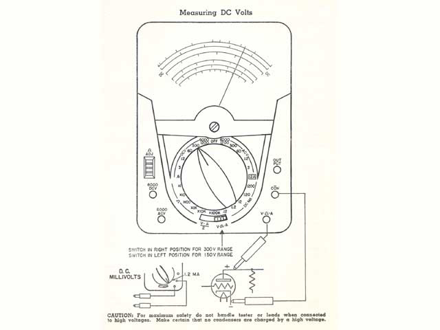
CAUTION on DC Volts do not measure DC voltages having an AC component greater than 450 volts peak. Insulation is tested to withstand a maximum of 1650 rms volts.
Connect the test prods ACROSS the voltage source. The red lead is positive. Where polarity is difficult to determine, the meter may read backwards. No damage will be done if this occurs. Simply reverse the leads.
All DC ranges are read on the two black center scales; one directly above the mirror, the other just below the mirror.
With Slide Switch In V-OHM-A Position:
The full scale reading of the instrument is identical to that indicated by the large range switch knob.
Thus with the range switch knob at 3 note that the 3 volt range is read on the 300 volt scale simply by dropping two zeros (i. e. dividing by 100). Other ranges are read similarly by adding or omitting zeros as required.
The meter sensitivity is 10,000 ohms per volt with slide switch in V-OHM-A position.
With Slide Switch In V-A/2 Position:
The instrument will read exactly half of the value indiÂcated by the large range switch knob. Thus with the range knob set at 300, the meter actually will read 150. The scale immediately above the mirror is used for 0-150 volts. With the range switch knob set on 60, the meter will read 30 volts full scale.
Read this on the 300 volt scale by dropping one zero (ie. dividing by 10). Other ranges are handled in a similar fashion. The meter sensitivity is 20,000 ohms per volt with the slide switch in V-A/2 position.
In order to read D. C. millivolts, the lull scale value will be 240 mV with the slide switch to the right and 120 mV with the slide switch to the loft, when placing the knob of the selector switch in the .12 or 1.2 D. C. ma ranges for either of the mV readings. Sensitivity will not be 10.000 OHMS/V and 20.000 OHMS/V at 240 mV and 120 mV respectively.
Rotate the selector switch to the appropriate range for DC volts. Always start with the highest range if in doubt as to the approximate voltage. In choosing ranges, endeavor to have the readings fall in the upper, or right hand, half of the scale for greatest accuracy.
Plug the black test lead into the "COM" jack and the red lead into the V-OHM-A jack as shown in the image.
CAUTION on DC Volts do not measure DC voltages having an AC component greater than 450 volts peak. Insulation is tested to withstand a maximum of 1650 rms volts.
Connect the test prods ACROSS the voltage source. The red lead is positive. Where polarity is difficult to determine, the meter may read backwards. No damage will be done if this occurs. Simply reverse the leads.
All DC ranges are read on the two black center scales; one directly above the mirror, the other just below the mirror.
With Slide Switch In V-OHM-A Position:
The full scale reading of the instrument is identical to that indicated by the large range switch knob.
Thus with the range switch knob at 3 note that the 3 volt range is read on the 300 volt scale simply by dropping two zeros (i. e. dividing by 100). Other ranges are read similarly by adding or omitting zeros as required.
The meter sensitivity is 10,000 ohms per volt with slide switch in V-OHM-A position.
With Slide Switch In V-A/2 Position:
The instrument will read exactly half of the value indiÂcated by the large range switch knob. Thus with the range knob set at 300, the meter actually will read 150. The scale immediately above the mirror is used for 0-150 volts. With the range switch knob set on 60, the meter will read 30 volts full scale.
Read this on the 300 volt scale by dropping one zero (ie. dividing by 10). Other ranges are handled in a similar fashion. The meter sensitivity is 20,000 ohms per volt with the slide switch in V-A/2 position.
In order to read D. C. millivolts, the lull scale value will be 240 mV with the slide switch to the right and 120 mV with the slide switch to the loft, when placing the knob of the selector switch in the .12 or 1.2 D. C. ma ranges for either of the mV readings. Sensitivity will not be 10.000 OHMS/V and 20.000 OHMS/V at 240 mV and 120 mV respectively.
#12
The Maintenance Saloon / Re: Triplett 630-NA Meter
September 09, 2017, 05:56:AM
I actually have a copy of the manual, I'll try to post the good stuff here for reading material but I'm not actually looking at parting with it.
#13
The Maintenance Saloon / Re: Welcome to the Obsolete Industrial Roundtable
February 04, 2016, 04:43:AM
Hello,
I stumbled on the maintenance forum here. Pretty good idea...
I stumbled on the maintenance forum here. Pretty good idea...
Pages1