
Well done, measuring inverter output voltage has always been a grey area and I usually don't bother. This seems like it is worth a try just for an experiment.
- Welcome to OI Roundtable.

The Maintenance Technicians App
This section allows you to view all posts made by this member. Note that you can only see posts made in areas you currently have access to.
Pages1
#2
Electrical and Electronic / Re: Simple Frequency Drive Diagram
January 18, 2019, 03:56:AM
There was actually a good intro to variable frequency drives that accompanied the diagram, so here it is:
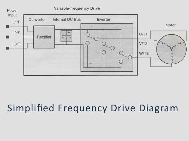
Define the Inverter / Variable Freq. Drive
The term inverter and variable frequency drive are related and somewhat interchangeable. An
electronic drive for an AC motor controls the motor's speed by varying the frequency of the
power sent to the motor.
An inverter, in general, is a device that converts DC power to AC power. The diagram shows how the variable-frequency drive employs an internal inverter.
The drive first converts incoming AC power to DC through a rectifier bridge, creating an internal DC bus voltage. Then the inverter circuit converts the DC back to AC again to power the motor. The special inverter can vary its output frequency and voltage according to the desired motor speed.
The simplified diagram of the inverter shows three double-throw switches. The switches are actually IGBTs (Isolated Gate Bipolar Transistors). Using a commutation algorithm, the microprocessor in the drive switches the IGBTs ON and OFF at a very high speed to create the desired output wave forms. The inductance of the motor windings helps smooth out the pulses.
#3
The Maintenance Saloon / Re: Condenser Tester
January 17, 2019, 04:33:AM
Condenser or capacitor tester, you be the judge...
#4
The Maintenance Saloon / Re: Old vacuum Tubes
January 17, 2019, 04:33:AM
Hobbyists still use vacuum tubes but I would say their use in the real world has all but disappeared.
#5
The Maintenance Saloon / Re: Old Triplett Meters
January 17, 2019, 04:31:AM
Seems as though Triplett meters were always second to Simpson brand meters. However they worked just as well as far as I'm concerned.
#6
The Maintenance Saloon / Re: Old Radiation Meter
January 17, 2019, 04:30:AM
RCA made one heck of a radiation meter. Just sayin'
#7
Electrical and Electronic / Simple Frequency Drive Diagram
January 17, 2019, 04:29:AM
I thought this was a cool depiction of a variable frequency drive.
Sometimes when systems are dumbed down like this, they are easier to comprehend.
Sometimes when systems are dumbed down like this, they are easier to comprehend.
#8
The Maintenance Saloon / Re: All-Meter
January 17, 2019, 04:24:AM
These ads are cool. Technology has changed big time in some areas and not so much in others.
These meters look remarkably similar throughout the decades. I've never seen this particular All-Meter brand of multimeter but it resembles the S260 meter.
These meters look remarkably similar throughout the decades. I've never seen this particular All-Meter brand of multimeter but it resembles the S260 meter.
#9
E-Market and Web / Re: Wanted: Durant 1200-811
January 17, 2019, 04:20:AM
These Durant counters are most likely obsolete, an updated version may be available or you can probably engineer something else.
#10
Electrical and Electronic / What is a Proboscope?
February 05, 2018, 04:16:AM
Guys,
What is a Proboscope and what purpose does it serve? I have a proboscope on the shelf here and it hasn't seen any service since I have been employed here. I don't know if this is a piece of test equipment that is designed to test a certain piece of electronics or is it something that can be used for every day troubleshooting.
Thank You!
#11
Electrical and Electronic / Re: Industrial computer shuts down with battery backup
October 19, 2015, 02:52:PM
I think you have a sensitive power supply. I have heard that some of the newer computer power supplies do not like the battery backup outputs. If it were a standard power supply in your industrial computer, maybe you could swap it out with an older power supply and see what happens... a little test...
#12
The Maintenance Saloon / Re: Do you Prefer an Oscilloscope or a Scopemeter
October 19, 2015, 02:49:PMQuote from: Cheller on October 03, 2015, 04:10:AM
Well... the veteran maintenance techs and electricians may be used to the old CRT style oscilloscopes, but are they better than a modern scopemeter? Which do you prefer for diagnosing electronic problems that include tricky waveforms?
I voted for the scopemeter just because I like newer technology. I think you can solve problems with either one as long as you are familiar with them.
#13
Troubleshooting 101 / Re: What is a harmonic neutralizer in a transformer?
October 19, 2015, 02:47:PMQuote from: jackson6 on October 17, 2015, 11:07:AM
What is a harmonic neutralizer in a transformer? I have an older 1KVA unit I'd like to use and I don't ever recall seeing a tansformer with a harmonic neutralizer before.
What is a harmonic neutralizer?
Well, it is a circuit designed to neutralize harmonic currents. Harmonic currents, or harmonics as they are better known, are a result of a distorted electrical waveform, generally created by non-linear loads. That's the technical end of things, I guess.
Some of the more common causes of unwanted harmonics are variable speed motors, variable frequency drives and inverters, industrial battery chargers, some personal computers, and even those small portable uninterruptable power supplies.
So harmonic neutralizers can be incorporated into some constant voltage transformers primarily to clean up harmonic distortion. To keep it simple, these neutralizer basically absorb harmonic power and emit heat as a by-product.
I really don't see why you couldn't use a transformer with a harmonic neutralizer for an application that doesn't have a harmonic problem. I look at it like a noise filter. The rating of the transformer should still hold true regardless of any capacitors or internal circuit.
#14
Troubleshooting 101 / Re: Welcome to the Roundtable!
October 09, 2015, 03:29:PM
So far so good... I like it. A forum dedicated to maintenance electricians and maintenance mechanics.
#15
Troubleshooting 101 / Re: Do I need a true RMS multi-meter?
October 09, 2015, 03:28:PM
I used what I thought was a good Fluke meter for many years. I broke down and bought a True RMS meter and after using it for just a few months, I know I'll never go back. I feel better about the readings when working with variable drives. That alone makes it all worth it.
You can get good deals on eBay. I think you'll find the best values there whether you buy a used one or go with new.
You can get good deals on eBay. I think you'll find the best values there whether you buy a used one or go with new.
#16
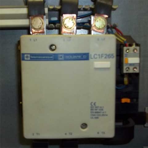
Troubleshooting 101 / Re: What is the Best Way to Test a 3 Pole Contactor
October 09, 2015, 03:25:PM
The best way to test a 3 pole contactor is .... very carefully. 
Actually, testing a 3 pole contactor is not hard at all. A contactor is an electrically controlled switch, it's also referred to as a relay. They are used for switching a power circuit on and off with a separate voltage supply. The design of the contactor enables it to be opened and closed repeatedly with minimal damage on the high current contacts.
First... Testing the contacts for failure
In a perfect world, these contacts last forever. This is directly related to design and the load on the contacts, as well as the frequency at which they are opened and closed under load.
So these higher current contacts can fail in an open position, burnt or melted as a result of the contactor being under- sized or as a result of a shorted load creating a high current situation. Power down the system on which you are working, remember to follow local laws regarding lockout/tagout where required. it is your responsibility to use safe work practices.
With power verified off, tag and remove the power leads from the high current side of the contactor. Essentially you'll be disconnecting all the wires on the 3 pole contacts. If you can manually operate the contactor with your fingers or a hand tool, you can test the contactors with an ohmmeter. High ohms nearing infinity when the contactor is open, low ohms or shorted to 0 when you manually engage the contacts.
Again, this is done with the power off. This should give you the answer you've been looking for... if not, continue testing your 3 pole contactor, this time under power....
Reconnect the feeding side of the contacts and keep the load side disconnected. Safely energize the coil control circuit and check for the appropriate voltage on the load terminals. Adjust your multimeter for volts. Are all three phases showing up when the contactor is energized?
By this time you would have determined if one or more of the high current contacts have failed. On the older obsolete contactors, the contacts may actually be exposed and you can visibly see the damage. Newer models may not be so easy to disassemble.
Other problems you may encounter on a 3 pole contactor, include mechanical failure such as broken or missing return springs, even a worn frame of the contactor. Most of the time a visual inspection is enough to find problems like these.
You'll see more failures occur due to excessive heat or after the service life of the contactor has been exceeded.
Testing the contactor coil is another story, again not too awful.
More commonly, a failed coil can be the source of an inoperable contactor. This is typically the root cause when a 3 pole contactor fails to energize event though voltage is being supplied to the coil.
It is tested in either of two ways. First, in a power-on scenario, a check of the voltage at the coil terminals should give an instant answer as to whether the coil is being electrically energized.
On contactors with overload resets, you will have to check the overload circuit for failure or an open circuit if you do not read the appropriate voltage directly from the coil terminals. It can be a tripped overload preventing the coil from being energized.
Of course you should verify the voltage with the label or nameplate on the coil also. This ensures that the proper voltage is being applied.
In a power-off situation, you can check for coil continuity using an ohmmeter. Be sure to safely power down the circuit (or the entire machine), select a low ohm setting on your multi-meter and check directly on the coil's terminals.
An open circuit (or very high resistance) signifies an open coil; a moderate resistance would indicate that the coil is capable of conducting electricity. A reading of 0 ohms, however, could indicate a short circuit of the coil but this is more of a rarity since energizing a shorted coil usually amounts to excessive current and heating of the coil until it fails.
Testing 3 pole contactors is not entirely simple nor is it too difficult either, yet even a seasoned maintenance technician can get confused every now and then. I think these are some good basic rules for testing.
Pages1