
- Welcome to OI Roundtable.

The Maintenance Technicians App
This section allows you to view all posts made by this member. Note that you can only see posts made in areas you currently have access to.
#2
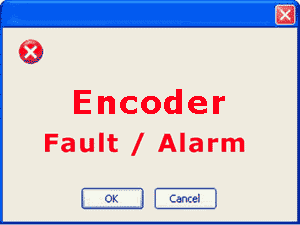
Troubleshooting 101 / Re: What is the easiest way to test an encoder?
April 26, 2024, 05:28:AM
Good info, I thought it was worth bumping.
#3
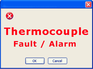
Troubleshooting 101 / Re: Troubleshooting a Thermocouple Ground Loop
April 26, 2024, 04:43:AM
Good work on the thermocouple tests...
#4
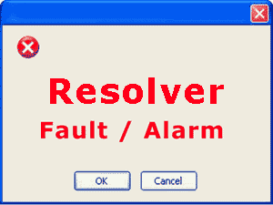
Troubleshooting 101 / Re: What is the easiest way to test a resolver?
April 26, 2024, 04:38:AM
Nice job with the resolver testing. These are black boxes to a lot of people who just swap parts.
#9
Troubleshooting 101 / Re: A06B DC Servo Faults
April 23, 2024, 04:33:AM
Thanks for the DC Servo fault list, should be a big help.
#10
Troubleshooting 101 / Re: Fanuc Series 0 Servo Faults and Alarm Codes
April 23, 2024, 04:32:AM
Thanks for the Fault Listing!
#11
Troubleshooting 101 / Re: Fanuc 0-T and 0-M Faults, Errors, Alarms
April 23, 2024, 04:30:AM
Nice Job with the Fanuc fault list!
#12
Troubleshooting 101 / Re: Fanuc A06B Alarms and Faults
April 23, 2024, 04:29:AM
Nice work on the A06B Faults!
#13
Troubleshooting 101 / Re: FANUC Spindle Module Alarms, Errors, and Faults
April 23, 2024, 04:28:AM
Looks good! "FANUC Spindle Faults, Alarms, and Errors"
#14
Troubleshooting 101 / Re: ABB ACS160 Alarm Codes and Fault Codes
February 22, 2024, 03:56:AM
Great job with the code lists for the 160 drive! These posts are helpful for quick alarm reference.
#15
The Maintenance Saloon / Re: Power Tech Drive Reviews
February 18, 2024, 07:14:AM
Where are Power Tech drives made? This is where I would start this conversation. Country of manufacture matters when I buy any drive for any application. Power Tech isn't a very popular brand.
#16
Electrical and Electronic / Re: Cutler Hammer Contactor Tips
February 18, 2024, 07:11:AM
I actually had some recent experience with Cutler hammer contactors. I purchased an aftermarket Cutler Hammer contact kit that is coated with a silver alloy. I double checked the size and the load on the contactor and everything checks out within spec. All I can do is wait it out and see how it holds up. They were made in Mexico. It would be hard to tell at this point if these contacts are any good.
#17
Troubleshooting 101 / Re: ABB ACS140 Fault, Alarm, and Error Codes
February 18, 2024, 07:06:AM
Again, nice job with these code lists for the 140 drive!
#18
Troubleshooting 101 / Re: ABB ACS100 Fault Alarm and Error Help
February 18, 2024, 07:02:AM
Again, nice job with these code lists!
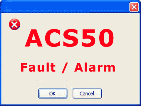
#19
Troubleshooting 101 / Re: ABB ACS50 Faults, Errors, and Alarms
January 23, 2024, 04:42:AM
Nice job!
#20
Troubleshooting 101 / Re: Simovert Masterdrive Faults
September 27, 2022, 03:31:AM
And so it continues, these are the technology board faults, not a lot of info with these here because as you can see from this part of the list, you'll need to look at the tech board manual...
- F116 Technology board fault (not Compact PLUS) - cause: See TB documentation - remedy/suggestion: See Technology Board documentation
- F117 Technology board fault (not Compact PLUS) - cause: See TB documentation - remedy/suggestion: See Technology Board documentation
- F118 Technology board fault (not Compact PLUS) - cause: See TB documentation - remedy/suggestion: See Technology Board documentation
- F119 Technology board fault (not Compact PLUS) - cause: See TB documentation - remedy/suggestion: See Technology Board documentation
- F120 Technology board fault (not Compact PLUS) - cause: See TB documentation - remedy/suggestion: See Technology Board documentation
- F121 Technology board fault (not Compact PLUS) - cause: See TB documentation - remedy/suggestion: See Technology Board documentation
- F122 Technology board fault (not Compact PLUS) - cause: See TB documentation - remedy/suggestion: See Technology Board documentation
- F123 Technology board fault (not Compact PLUS) - cause: See TB documentation - remedy/suggestion: See Technology Board documentation
- F124 Technology board fault (not Compact PLUS) - cause: See TB documentation - remedy/suggestion: See Technology Board documentation
- F125 Technology board fault (not Compact PLUS) - cause: See TB documentation - remedy/suggestion: See Technology Board documentation
- F126 Technology board fault (not Compact PLUS) - cause: See TB documentation - remedy/suggestion: See Technology Board documentation
- F127 Technology board fault (not Compact PLUS) - cause: See TB documentation - remedy/suggestion: See Technology Board documentation
- F128 Technology board fault (not Compact PLUS) - cause: See TB documentation - remedy/suggestion: See Technology Board documentation
- F129 Technology board fault (not Compact PLUS) - cause: See TB documentation - remedy/suggestion: See Technology Board documentation
- F130 Technology board fault (not Compact PLUS) - cause: See TB documentation - remedy/suggestion: See Technology Board documentation
- F131 Technology board fault (not Compact PLUS) - cause: See TB documentation - remedy/suggestion: See Technology Board documentation
- F132 Technology board fault (not Compact PLUS) - cause: See TB documentation - remedy/suggestion: See Technology Board documentation
- F133 Technology board fault (not Compact PLUS) - cause: See TB documentation - remedy/suggestion: See Technology Board documentation
- F134 Technology board fault (not Compact PLUS) - cause: See TB documentation - remedy/suggestion: See Technology Board documentation
- F135 Technology board fault (not Compact PLUS) - cause: See TB documentation - remedy/suggestion: See Technology Board documentation
- F136 Technology board fault (not Compact PLUS) - cause: See TB documentation - remedy/suggestion: See Technology Board documentation
- F137 Technology board fault (not Compact PLUS) - cause: See TB documentation - remedy/suggestion: See Technology Board documentation
- F138 Technology board fault (not Compact PLUS) - cause: See TB documentation - remedy/suggestion: See Technology Board documentation
- F139 Technology board fault (not Compact PLUS) - cause: See TB documentation - remedy/suggestion: See Technology Board documentation
- F140 Technology board fault (not Compact PLUS) - cause: See TB documentation - remedy/suggestion: See Technology Board documentation
- F141 Technology board fault (not Compact PLUS) - cause: See TB documentation - remedy/suggestion: See Technology Board documentation
- F142 Technology board fault (not Compact PLUS) - cause: See TB documentation - remedy/suggestion: See Technology Board documentation
- F143 Technology board fault (not Compact PLUS) - cause: See TB documentation - remedy/suggestion: See Technology Board documentation
- F144 Technology board fault (not Compact PLUS) - cause: See TB documentation - remedy/suggestion: See Technology Board documentation
- F145 Technology board fault (not Compact PLUS) - cause: See TB documentation - remedy/suggestion: See Technology Board documentation
- F146 Technology board fault (not Compact PLUS) - cause: See TB documentation - remedy/suggestion: See Technology Board documentation
- F147 Technology board fault (not Compact PLUS) - cause: See TB documentation - remedy/suggestion: See Technology Board documentation
#21
Troubleshooting 101 / Re: Simovert Masterdrive Faults
September 21, 2022, 04:03:AM
This is Masterdrive Fault 74 to 82
- F074 AnInp2 SL1 (not Compact PLUS) - cause: 4 mA at analog input 2, slave 1 fallen short of - remedy/suggestion: Check the connection of the signal source to the SCI1 (slave 1) -X428: 7, 8
- F075 AnInp3 SL1 (not Compact PLUS) - cause: 4 mA at analog input 3, slave 1 fallen short of - remedy/suggestion: Check the connection of the signal source to the SCI1 (slave 1) -X428: 10, 11
- F076 AnInp1 SL2 (not Compact PLUS) - cause: 4 mA at analog input 1, slave 2 fallen short of - remedy/suggestion: Check the connection of the signal source to the SCI1 (slave 2) -X428: 4, 5
- F077 AnInp2 SL2 (not Compact PLUS) - cause: 4 mA at analog input 2, slave 2 fallen short of - remedy/suggestion: Check the connection of the signal source to the SCI1 (slave 2) -X428: 7, 8
- F078 AnInp3 SL2 (not Compact PLUS) - cause: 4 mA at analog input 3, slave 2 fallen short of - remedy/suggestion: Check the connection of the signal source to the SCI1 (slave 2) -X428: 10, 11
- F079 SCB telegram failure (not Compact PLUS) - cause: No telegram has been received by the SCB(USS, peer-to-peer, SCI) within the telegram failure time - remedy/suggestion: Check the connections of the SCB1(2), Check P704.03"SCom/SCB Tlg OFF", Replace SCB1(2), or Replace CU (-A10)
- F080 TB/CB initialization fault- cause: Fault during initialization of the board at the DPR interface - remedy/suggestion: Fault value r949:
1: Board code incorrect
2: TB/CB board not compatible
3: CB board not compatible
5: Error in configuration data
6: Initialization timeout
7: TB/CB board double
10: Channel error
Check the T300/CB board for correct contacting, check the PSU power supply, check the CU / CB / T boards and check the CB initialization parameters: P918.01 CB Bus Address, and P711.01 to P721.01 CB parameters 1 to 11 - F081 OptBrdHeartbeat-Counter - cause: Heartbeat-counter of the optional board is no longer being processed - remedy/suggestion: Fault value r949:
0: TB/CB heartbeat-counter
1: SCB heartbeat-counter
2: Additional CB heartbeat-counter
Acknowledge the fault (whereby automatic reset is carried out), If the fault re-occurs, replace the board concerned (see fault value), Replace ADB, Check the connection between the subrack and the optional boards (LBA) and replace, if necessary - F082 TB/CB telegram failure - cause: No new process data have been received by the TB or the CB within the telegram failure time - remedy/suggestion: Fault value r949:
1 = TB/CB
2 = additional CB
Check the connection to TB/CB, Check P722 (CB/TB TlgOFF), Replace CB or TB - F085 Add. CB initialization fault - cause: A fault has occurred during initialization of the CB board. - remedy/suggestion: Fault value r949:
1: Board code incorrect
2: TB/CB board not compatible
3: CB board not compatible
5: Error in configuration data
6: Initialization timeout
7: TB/CB board double
10: Channel error
Check the T300 / CB board for correct contacting and check the CB initialization parameters: P918.02 CB Bus Address, P711.02 to P721.02 CB Parameters 1 to 11 - F087 SIMOLINK initialization fault - cause: A fault has occurred during initialization of the SLB board - remedy/suggestion: Replace CU (-A10), or replace the unit(Compact PLUS type), or Replace SLB
- F099 Friction characteristic record - cause: Recording of the friction characteristic was interrupted or not done at all - remedy/suggestion:
- F109 Mld R(L) - cause: The rotor resistance determined during measurement of the direct current deviates too greatly - remedy/suggestion: Repeat measurement, Enter data manually
- F111 MId DSP - cause: A fault has occurred during the Mot Id.
r949=1 The current does not build up when voltage pulses are applied
r949=2 (only for P115=4) The difference between speed setpoint and actual value is too large during measurement
r949=3 (only for P115=4) The magnetizing current determined is too high.
r949=121 The stator resistance P121 is not determined correctly
r949=124 The rotor time constant P124 is parameterized with the value 0 ms
r949=347 The valve voltage drop P347 is not determined correctly - remedy/suggestion: Repeat measurement
When r949=1: Check motor cables, When r949=2: Avoid mechanical stressing of the motor during the measurement; if the fault occurs directly after the start of the motor identification check the encoder and motor cables, or When r949=3: Check the motor rating plate data stored (ratio Vrated / Irated does not correspond with the measured inductance - F112 Mid X(L) - cause: A fault has occurred during measurement of the motor inductances or leakages - remedy/suggestion: Repeat measurement
- F114 MId OFF - cause: The converter has automatically stopped the automatic measurement due to the time limit up to power-up having been exceeded or due to an OFF command during the measurement, and has reset the function selection in P115 - remedy/suggestion: Re-start with P115 function selection = 2 "Motor identification at standstill". The ON command must be given within 20 sec. after the alarm message A078 = standstill measurement has appeared.
Cancel the OFF command and re-start measurement.
- F109 Mld R(L) - cause: The rotor resistance determined during measurement of the direct current deviates too greatly - remedy/suggestion: Repeat measurement, Enter data manually
#22
Troubleshooting 101 / Re: Simovert Masterdrive Faults
September 17, 2022, 04:16:AM
Continuation of the Simovert Masterdrive Errors...
- F054 Encoder board initialization fault - cause: A fault has occurred during initialization of the encoder board - remedy/suggestion: Fault value r949:
1: Board code is incorrect
2: TSY not compatible
3: SBP not compatible
4: SBR not compatible
5: SBM not compatible (from V2.0 only theSBM2 board is supported; see also r826 function diagram 517)
6: SBM initialization timeout
7: Board double
20: TSY board double
21: SBR board double
23: SBM board three-fold
24: SBP board three-fold
30: SBR board slot incorrect
31: SBM board slot incorrect
32: SBP board slot incorrect
40: SBR board not present
41: SBM board not present
42: SBP board not present
50: Three encoder boards or two encoder boards, none of them onSlot C
60: internal fault - F056 SIMOLINK telegram failure - cause: Communication on the SIMOLINK ring is disturbed. - remedy/suggestion: Check the fiber-optic cable ring, Check whether an SLB in the ring is without voltage, Check whether an SLB in the ring is faulty, Check P741 (SLB TlgOFF)
- F058 Parameter fault Parameter task - cause: A fault has occurred during the processing of a parameter task - remedy/suggestion: No remedy for this
- F059 Parameter fault after factory setting/init - cause: A fault has occurred in the initialization phase during the calculation of a parameter - remedy/suggestion: The number of the inconsistent parameter isindicated in fault value r949. Correct this parameter (ALL indices) and switch voltage offand on again. Several parameters may be affected, i.e. repeat process
- F060 MLFB is missing during initial loading - cause: Is set if parameter P070 is at zero when INITIAL LOADING is exited - remedy/suggestion: Enter correct MLFB after acknowledging thefault (power section, initial loading
- F061 Incorrect parameterization - cause: A parameter which has been entered during drive setting is in the non-permissible range - remedy/suggestion: The number of the inconsistent parameter is indicated in fault value r949 (e.g. motor encoder = pulse encoder in the case of brushless DC motors) -> correct this parameter
- F063 PIN is missing- cause: The synchronization or positioning technology functions have been activated without an authorization being present (PIN) - remedy/suggestion: Deactivate synchronization or positioning, Enter the PIN (U2977)
If technology functions are inserted in the timeslots without enabling the technology function through the PIN, the message F063 is generated. This fault can only be cleared by putting in the correct PIN at U977.01 and U977.02 and switching the power off and on again, or by disabling the technology functions (put U953.32 = 20 and U053.33 = 20) - F065 SCom telegram failure - cause: No telegram has been received at an SCom interface (SCom/USS protocol) within the telegram failure time - remedy/suggestion: Fault value r949:
1 = Interface 1 (SCom1)
2 = Interface 2 (SCom2)
Check the connection of PMU -X300 or X103 /27,28 (Compact, chassis unit)
Check the connection of X103 or X100 / 35,36(Compact PLUS unit)
Check "SCom/SCB TlgOff" P704.01 (SCom1)or P704.02 (SCom2) - F070 SCB initialization fault - cause: A fault has occurred during initialization of the SCB board - remedy/suggestion: Fault value r949:
1: Board code incorrect
2: SCB board not compatible
5: Error in configuration data(Check parameterization)
6: Initialization timeout
7: SCB board double
10: Channel error - F072 EB initialization fault - cause: A fault has occurred during initialization of the EB board. - remedy/suggestion: Fault value r949:
2: 1st EB1 not compatible
3: 2nd EB1 not compatible
4: 1st EB2 not compatible
5: 2nd EB2 not compatible
21: Three EB1 boards
22: Three EB2 boards
110: Fault on 1st EB1
120: Fault on 2nd EB1
210: Fault on 1st EB2
220: Fault on 2nd EB2 - F073 AnInp1SL1not Compact PLUS - cause: 4 mA at analog input 1, slave 1 fallen short of - remedy/suggestion: Check the connection of the signal source to the SCI1 (slave 1) -X428: 4, 5
#23
Troubleshooting 101 / Re: Simovert Masterdrive Faults
September 16, 2022, 03:37:AM
This is the Simovert encoder fault, it's one of the more common Simovert faults:
Additional Simovert alarms follow in additional posts...
- F051 Encoder fault - cause: Signal amplitude of resolver or encoder is below the tolerance threshold, Power supply faults in the case of encoders and multiturn encoders, In the case of multiturn encoders (SSI/Endat), connection fault of the serial protocol - remedy/suggestion: Fault value r949:10th and 1st position: 9 = Resolver signal missing (sin/cos track)
20 = Position error: Alarm A18 was generatedduring the change to the "operation" state.(For remedial action see 29)
21 = A/B track undervoltage:Root(A^2+B^2)<0.01V (For remedial actionsee 29)
22 = A/B track overvoltage:Root(A^2+B^2)>1.45V (For remedial actionsee 29)
25 = Encoder initial position not recognized(C/D track missing), Check encoder cable (faulty / interrupted)? Correct encoder type parameterized? Is the correct cable used for encoder ormultiturn encoder? Encoders and multiturn encoders need different cables!, Encoder faulty?
26 = Encoder zero pulse outside the permitted range
27 = No encoder zero pulse has occurred
28 = Encoder/multiturnVoltage supply Encoder fault, Short-circuit in encoder connection? Encoder faulty? Encoder incorrectly connected up?! Power off/on or in drive settings and back to new initialization of the starting position!
29 = A/B track undervoltage: In the zero passage of one track the amount of the other track was less than 0.025 V, Check encoder cable (faulty/torn off)? Is shield of encoder cable connected ? Encoder faulty? Replace SBR/SBM Replace unit or basic board, Is the correct cable being used in each case for the encoder/multiturn encoder? Encoders and multiturn encoders require different encoder cables! Power off/on or in drive settings and back to new initialization of the starting position!
Multiturn (SSI/EnDat):
30: Protocol fault CRC/Parity Check (EnDat)
31: Timeout Protocol (EnDat)
32: No-load level error, data line (SSI/EnDat)
33: Initialization of timeout, Check parameterization (P149), Check encoder cable (faulty / torn off? Encoder cable shield connected? Encoder faulty? Replace SBR/SBM, Replace unit or basic board
34: Address wrong (only EnDat)- Writing or reading of parameters not successful, check address and MRS code(P149)
35: The difference between the serial protocol and the pulse counter is greater than 0xFFFF(2^16). A possible fault may be a jump in the serial protocol. The fault can only be generated if an absolute encoder with incremental tracks (P149.01/.06 = X1XX) and multiturn portion is concerned. (EnDat)
40: Alarm, lighting, EnDat encoder
41: Alarm, signal amplitude, EnDat encoder
42: Alarm. position value, EnDat encoder
43: Alarm, overvoltage, EnDat encoder
44: Alarm, undervoltage, EnDat encoder
45: Alarm, overcurrent, EnDat encoder
46: Alarm, battery failure, EnDat encoder
49: Alarm, check sum error, EnDat encoder
60: SSI protocol faulty (see P143)
100th position:0xx: Motor encoder faulty1xx: External encoder faulty
1000th position: (from V1.50)
1xxx: Frequency exceeded, EnDat encoder
2xxx: Temperature, EnDat encoder
3xxx: Control reserve, light, EnDat encoder
4xxx: Battery charge, EnDat encoder5xxx: Home point not reached
Additional Simovert alarms follow in additional posts...
#24
Troubleshooting 101 / Simovert Masterdrive Faults
September 13, 2022, 04:42:AM
Simovert Masterdrive Faults
Remember: If a fault message is not reset before the supply voltage is switched off, then the fault message will be present again when the electronic supply is switched on again. The unit cannot be operated without resetting the fault message.
Note: This Simovert fault list continues in subsequent posts...
Remember: If a fault message is not reset before the supply voltage is switched off, then the fault message will be present again when the electronic supply is switched on again. The unit cannot be operated without resetting the fault message.
- F001 Main contactor checkback - cause: The monitoring time of the main contactor checkback (P600) has expired - remedy/suggestion: Check main contactor checkback, Clear main contactor checkback (P591.B = 0), or Increase monitoring time (P600)
- F002 Precharging fault - cause: The monitoring time of pre-charging has expired, i.e. the DC link voltage has not reached the setpoint within 3 secs - remedy/suggestion: Check voltage connection (AC or DC), Unit-dependent: Check fuses, or Compare value in P070 and unit MLFB
- F006 DC link overvoltage - cause: Due to excessive DC link voltage, shutdown has occurred. The rated value of the shutdown DC link overvoltage threshold is 819 V. Due to component tolerances shutdown can take place in the range from 803 V to 835 V. - remedy/suggestion: Check the line voltage (AC-AC) or the input direct voltage (DC-AC). Compare value withP071 (Line Volts)
- F008 DC link undervoltage - cause: The lower limit value of 76% of the DC link voltage has been fallen short of. In the fault value the DC link voltage upon occurrence of the fault is indicated (normalization 0x7FFF corresponds to 1000V) - remedy/suggestion: Check the line voltage (AC-AC) or the input direct voltage (DC-AC). Compare value with P071 (Line Volts), Check input rectifier (AC-AC), or Check DC link
- F011 Overcurrent not Compact PLUS - cause: Overcurrent shutdown has occurred. The shutdown threshold has been exceeded. The phase in which an overcurrent has occurred is indicated in a bit-coded manner in the fault value (see P949). Phase U --> Bit 0 = 1--> fault value = 1 Phase V --> Bit 1 = 1--> fault value = 2 Phase W--> Bit 2 = 1--> fault value = 4 If an overcurrent occurs simultaneously in several phases, the total of the fault values of the phases concerned is the resulting fault value- remedy/suggestion: Check the converter output for short-circuit or earth fault, Check the load for an overload condition, Check whether motor and converter are correctly matched, or Check whether the dynamic requirements are too high
- F015 Motor Blocked - cause: Motor is blocked/overloaded (current control), or has stalled (v/f characteristic): Static load is too high, The fault is not generated until after the time entered in P805, Binector B0156 is set, in status word 2 r553 Bit 28, Whether the drive is blocked or not can be detected at P792 (Perm Deviation) and P794. P806 enables detection to be limited to "atstandstill" (P806 = 1, only for current control) or to be completely de-activated (P806 = 2). In the case of current control, the precondition for this fault is that the torque limits (B0234) have been reached. In the case of slave drive, detection is de-activated. In the case of v/f control, the I(max) controller must be active - remedy/suggestion: Reduce the load, Release the brake, Increase current limits, Increase P805 Blocking Time, Increase the response threshold for the permissible deviation P792, Increase torque limits or torque setpoint, Check connection of motor phases including correct phase assignment/sequence for v/f characteristic only: Reduce rate of acceleration or Check characteristic setting
- F017 SAFE STOP (Compact PLUS only) - cause: SAFE STOP operating or failure of the 24 V power supply during operation (only for Compact PLUS units) - remedy/suggestion: Jumper applied for SAFE STOP? SAFE STOP checkback connected? On Compact PLUS units: check 24 V supply
- F020 Excess temperature of motor - cause: The motor temperature limit value has been exceeded. r949 = 1 Motor temperature limit value exceeded, r949 = 2 Short-circuit in the motor temperature sensor cable or sensor defective, r949 = 4 Wire break of motor temperature sensor cable or sensor defective - remedy/suggestion: Temperature threshold adjustable in P381!, P131 = 0 -> fault de-activated, Check the motor (load, ventilation etc.), The current motor temperature can be read in r009 (Motor Temperat.), or Check the sensor for cable break, short-circuit
- F021 Motor I2t - cause: Parameterized limit value of the I2t monitoring for the motor (P384.002) has been exceeded - remedy/suggestion: Check: Thermal time constant of motor P383 Mot ThermT-Const or motor I2t load limitP384.002. The I2t monitoring for the motor is automatically activated if P383 >=100s(=factory setting) and P381 > 220°C is set.Monitoring can be switched off by setting a value <100s in P383.
- F023 Excess temperature of inverter - cause: The limit value of the inverter temperature has been exceeded - remedy/suggestion: Measure the air intake and ambient temperature (Observe minimum and maximum ambient temperature from 0°C to 45°C!), Observe the derating curves at theta > 45 °C (Compact PLUS) or 40 degrees C, Check whether the fan is running, Check that the air entry and discharge openings are not restricted, In the case of units >= 22 kW acknowledgement is only possible after 1 minute
- F025 UCE upper switch/UCE Phase L1 - cause: For Compact PLUS units: UCE upper switch, For chassis type units: UCE Phase L1- remedy/suggestion: Check the converter outputs for earth fault, Check the switch for "SAFE STOP" on Compact units
- F026 UCE lower switch/UCE Phase L2 - cause: For Compact PLUS units: UCE lower switch, For Compact and chassis type units: UCE Phase L2 - remedy/suggestion: Check the converter outputs for earth fault, Check the switch for "SAFE STOP" on Compact units
- F027 Pulse resistor fault /UCE Phase L3 - cause: For Compact PLUS AC/AC units: Pulse resistance fault, For chassis type units: UCE Phase L3 - remedy/suggestion: Check the converter outputs for earth fault, Check the switch for "SAFE STOP" on Compact DC/DC units and chassis units with the option "SAFE STOP"
- F029 Meas. value sensing (Compact PLUS only) - cause: A fault has occurred in the measured value sensing system: (r949 = 1) Offset adjustment in phase L1 not possible, (r949 = 2) Offset adjustment in phase L3 not possible, (r949 = 3) Offset adjustment in phases L1and L3 not possible, (r949=65) Autom. Adjustment of the analog inputs is not possible - remedy/suggestion: Fault in measured value sensing, Fault in power section (valve cannot block), Fault on CU
- F035 External fault 1 - cause: Parameterizable external fault input 1 has been activated - remedy/suggestion: Check whether there is an external fault, Check whether the cable to the corresponding digital output is interrupted, P575 (Src No ExtFault1)
- F036 External fault 2 - cause: Parameterizable external fault input 2 has been activated - remedy/suggestion: Check whether there is an external fault, Check whether the cable to the corresponding digital output is interrupted, P576 (Src No ExtFault2)
- F038 Voltage OFF during parameter storage- cause: A voltage failure has occurred during a parameter task - remedy/suggestion: Re-enter the parameter. The number of the parameter concerned is indicated in fault valuer949
- F040 Internal fault of sequence control - cause: Incorrect operating status - remedy/suggestion: Replace the control board (CUMC) or the unit(Compact PUS).
- F041 EEPROM fault - cause: A fault has occurred during the storage of values in the EEPROM - remedy/suggestion: Replace the control board (CUMC) or the unit(Compact PLUS)
- F042 Time slot overflow - cause: The available calculating time of the time slot has been exceeded., At least 10 failures of time slots T2, T3, T4 orT5 (see also parameter r829.2 to r829.5) - remedy/suggestion: Reduce pulse frequency, Calculate individual blocks in a slower sampling time, The technology functions Synchronization (U953.33) and Positioning (U953.32) must not be enabled at the same time
- F043 DSP link - cause: The link to the internal signal processor is interrupted - remedy/suggestion: Reduce pulse frequency (perhaps caused by calculating time overflow), If fault re-occurs, replace the board/unit
The pulse frequency P340 should not be adjusted to values larger than 7.5 kHz (for60MHz - DSP) or 6 kHz (for 40MHz - DSP). If higher values are set, indices 12 to 19 have to be checked on visualization parameter r829.The indicated free calculating time of the DSP time slots always have to be greater than zero. If the calculating time is exceeded, this is also displayed by fault F043 (DSP coupling). Remedy: Reduce pulse frequency (P340) - F044 BICO manager fault - cause: A fault has occurred in the softwiring of binectors and connectors - remedy/suggestion: Fault value r949:>1000: Fault during connector softwiring>2000: Fault during binector softwiring, Voltage OFF and ON, Factory setting and new parameterization, Exchange the board1028: Link memory is full. The link area between the two processors is full. No further connectors can be transferred. Reduction of the linked connections between the two processors. Interface between the two processors is position control/setpoint conditioning i.e.softwires from and to the setpoint conditioning, position controller, speed controller, torque interface and current controller which are not necessary should be dissolved to reduce the link (value 0)
- F045 HW fault on optional boards - cause: A hardware fault has occurred during access to an optional board - remedy/suggestion: Replace CU board (Compact, chassis units), Replace the unit (Compact PLUS), Check the connection between the subrack and the optional boards, Replace optional boards
- F046 Parameter coupling fault - cause: A fault has occurred during the transfer of parameters to the DSP. - remedy/suggestion: If fault re-occurs, replace the board/unit
Note: This Simovert fault list continues in subsequent posts...
#25
The Maintenance Saloon / Re: Vintage Meter Movements
August 31, 2022, 03:35:AM
I launched a bunch or vintage ammeters and voltmeters a while back, I knew I should have hung onto them.
#26
Troubleshooting 101 / Re: Sinamics S120 Fault Codes
August 23, 2022, 03:56:AM
Continuation of Sinamic Fault list...
This portion of the Sinamic fault list contains mostly the the Encoder 1 alarms and Encoder 2 alarms.
There's alot here and it shows how much engineering has gone into the Sinamics system.
This portion of the Sinamic fault list contains mostly the the Encoder 1 alarms and Encoder 2 alarms.
- 231700<location>Encoder 1: Effectivity test does not supply the expected value
- 231800<location>Encoder 1: Group signal
- 231801<location>Encoder 1 DRIVE-CLiQ: Sign-of-life missing
- 231802<location>Encoder 1: Time slice overflow
- 231804<location>Encoder 1: Checksum error
- 231805<location>Encoder 1: EPROM checksum error
- 231806<location>Encoder 1: Initialization error
- 231811<location>Encoder 1: Encoder serial number changed
- 231812<location>Encoder 1: Requested cycle or RX-/TX timing not supported
- 231813<location>Encoder 1: Hardware logic unit failed
- 231820<location>Encoder 1 DRIVE-CLiQ: Telegram error
- 231835<location>Encoder 1 DRIVE-CLiQ: Cyclic data transfer error
- 231836<location>Encoder 1 DRIVE-CLiQ: Send error for DRIVE-CLiQ data
- 231837<location>Encoder 1 DRIVE-CLiQ: Component fault
- 231845<location>Encoder 1 DRIVE-CLiQ: Cyclic data transfer error
- 231850<location>Encoder 1: Encoder evaluation, internal software error
- 231851<location>Encoder 1 DRIVE-CLiQ (CU): Sign-of-life missing
- 231860<location>Encoder 1 DRIVE-CLiQ (CU): Telegram error
- 231885<location>Encoder 1 DRIVE-CLiQ (CU): Cyclic data transfer error
- 231886<location>Encoder 1 DRIVE-CLiQ (CU): Error when sending DRIVE-CLiQ data
- 231887<location>Encoder 1 DRIVE-CLiQ (CU): Component fault
- 231895<location>Encoder 1 DRIVE-CLiQ (CU): Alternating cyclic data transfer error
- 231896<location>Encoder 1 DRIVE-CLiQ (CU): Inconsistent component properties
- 231899<location>Encoder 1: Unknown fault
- 231902<location>Encoder 1: SPI-BUS error occurred
- 231903<location>Encoder 1: I2C-BUS error occurred
- 231905<location>Encoder 1: Parameterization error
- 231915<location>Encoder 1: Configuration error
- 231916<location>Encoder 1: Parameterization fault
- 231920<location>Encoder 1: Temperature sensor fault
- 231999<location>Encoder 1: Unknown alarm
- 232100<location>Encoder 2: Zero mark distance error
- 232101<location>Encoder 2: Zero marked failed
- 232103<location>Encoder 2: Amplitude error, track R
- 232110<location>Encoder 2: Serial communications error
- 232111<location>Encoder 2: Absolute encoder EnDat, internal fault/error
- 232112<location>Encoder 2: Error bit set in the serial protocol
- 232115<location>Encoder 2: Amplitude error track A or B (A^2 + B^2)
- 232116<location>Encoder 2: Amplitude error monitoring track A + B
- 232117<location>Encoder 2: Inversion error signals A and B and R
- 232118<location>Encoder 2: Speed difference outside the tolerance range
- 232120<location>Encoder 2: Power supply voltage fault
- 232121<location>Encoder 2: Coarse position error
- 232122<location>Encoder 2: Internal power supply voltage faulty
- 232123<location>Encoder 2: Signal level A/B unipolar outside tolerance
- 232125<location>Encoder 2: Amplitude error track A or B overcontrolled
- 232126<location>Encoder 2: Amplitude AB too high
- 232129<location>Encoder 2: Position difference, hall sensor/track C/D and A/B too large
- 232130<location>Encoder 2: Zero mark and position error from the coarse synchronization
- 232131<location>Encoder 2: Deviation, position incremental/absolute too large
- 232135<location>Encoder 2: Fault when determining the position
- 232136<location>Encoder 2: Error when determining multiturn information
- 232137<location>Encoder 2: Internal error when determining the position
- 232138<location>Encoder 2: Internal error when determining multiturn information
- 232150<location>Encoder 2: Initialization error
- 232151<location>Encoder 2: Encoder speed for initialization AB too high
- 232160<location>Encoder 2: Analog sensor channel A failed
- 232161<location>Encoder 2: Analog sensor channel B failed
- 232400<location>Encoder 2: Alarm threshold zero mark distance error
- 232401<location>Encoder 2: Alarm threshold zero marked failed
- 232405<location>Encoder 2: Temperature in the encoder evaluation inadmissible
- 232407<location>Encoder 2: Function limit reached
- 232410<location>Encoder 2: Serial communications
- 232411<location>Encoder 2: EnDat encoder signals alarms
- 232412<location>Encoder 2: Error bit set in the serial protocol
- 232414<location>Encoder 2: Amplitude error track C or D (C^2 + D^2)
- 232415<location>Encoder 2: Amplitude alarm track A or B (A^2 + B^2)
- 232418<location>Encoder 2: Speed difference per sampling rate exceeded
- 232419<location>Encoder 2: Track A or B outside the tolerance range
- 232421<location>Encoder 2: Coarse position error
- 232422<location>Encoder 2: Pulses per revolution square-wave encoder outside tolerance bandwidth
- 232429<location>Encoder 2: Position difference, hall sensor/track C/D and A/B too large
- 232431<location>Encoder 2: Deviation, position incremental/absolute too large
- 232432<location>Encoder 2: Rotor position adaptation corrects deviation
- 232442<location>Encoder 2: Battery voltage pre-alarm
- 232443<location>Encoder 2: Unipolar CD signal level outside specification
- 232460<location>Encoder 2: Analog sensor channel A failed
- 232461<location>Encoder 2: Analog sensor channel B failed
- 232462<location>Encoder 2: Analog sensor, no channel active
- 232470<location>Encoder 2: Soiling detected
- 232500<location>Encoder 2: Position tracking traversing range exceeded
- 232501<location>Encoder 2: Position tracking encoder position outside tolerance window
- 232502<location>Encoder 2: Encoder with measuring gear, without valid signals
- 232503<location>Encoder 2: Position tracking cannot be reset
- 232700<location>Encoder 2: Effectivity test does not supply the expected value
- 232800<location>Encoder 2: Group signal
- 232801<location>Encoder 2 DRIVE-CLiQ: Sign-of-life missing
- 232802<location>Encoder 2: Time slice overflow
- 232804<location>Encoder 2: Checksum error
- 232805<location>Encoder 2: EPROM checksum error
- 232806<location>Encoder 2: Initialization error
- 232811<location>Encoder 2: Encoder serial number changed
- 232812<location>Encoder 2: Requested cycle or RX-/TX timing not supported
- 232813<location>Encoder 2: Hardware logic unit failed
- 232820<location>Encoder 2 DRIVE-CLiQ: Telegram error
- 232835<location>Encoder 2 DRIVE-CLiQ: Cyclic data transfer error
- 232836<location>Encoder 2 DRIVE-CLiQ: Send error for DRIVE-CLiQ data
There's alot here and it shows how much engineering has gone into the Sinamics system.
#27
Troubleshooting 101 / Re: Sinamics S120 Fault Codes
August 22, 2022, 04:20:AM
Continuation of Sinamics alarms and errors...
This part of the error list contains some drive alarms, SI Motion MM alarms, CU alarms, PU alarms, Encoder 1 alarms.
This part of the error list contains some drive alarms, SI Motion MM alarms, CU alarms, PU alarms, Encoder 1 alarms.
- 230664<location>Error while booting
- 230665<location>SI MM: System is defective
- 230672<location>SI CU: Control Unit software incompatible
- 230680<location>SI Motion MM: Checksum error safety monitoring functions
- 230681<location>SI Motion MM: Incorrect parameter value
- 230682<location>SI Motion MM: Monitoring function not supported
- 230683<location>SI Motion MM: SOS/SLS enable missing
- 230685<location>SI Motion MM: Safely-Limited Speed limit value too high
- 230688<location>SI Motion MM: Actual value synchronization not permissible
- 230692<location>SI Motion MM: Incorrect parameter value encoderless
- 230693<location>SI MM: Safety parameter settings changed, warm restart/POWER ON required
- 230700<location>SI Motion MM: STOP A initiated
- 230701<location>SI Motion MM: STOP B initiated
- 230706<location>SI Motion MM: SBR limit exceeded
- 230707<location>SI Motion MM: Tolerance for safe operating stop exceeded
- 230708<location>SI Motion MM: STOP C initiated
- 230709<location>SI Motion MM: STOP D initiated
- 230711<location>SI MM MM: Defect in a monitoring channel
- 230712<location>SI Motion MM: Defect in F-IO processing
- 230714<location>SI Motion MM: Safely-Limited Speed exceeded
- 230798<location>SI Motion MM: Test stop running
- 230799<location>SI Motion MM: Acceptance test mode active
- 230800<location>Power unit: Group signal
- 230801<location>Power unit DRIVE-CLiQ: Sign-of-life missing
- 230802<location>Power unit: Time slice overflow
- 230804<location>Power unit: CRC
- 230805<location>Power unit: EPROM checksum error
- 230809<location>Power unit: Switching information not valid
- 230810<location>Power unit: Watchdog timer
- 230820<location>Power unit DRIVE-CLiQ: Telegram error
- 230835<location>Power unit DRIVE-CLiQ: Cyclic data transfer error
- 230836<location>Power unit DRIVE-CLiQ: Send error for DRIVE-CLiQ data
- 230837<location>Power unit DRIVE-CLiQ: Component fault
- 230845<location>Power unit DRIVE-CLiQ: Cyclic data transfer error
- 230850<location>Power unit: Internal software error
- 230851<location>Power unit DRIVE-CLiQ (CU): Sign-of-life missing
- 230853<location>Power unit: Sign-of-life error cyclic data
- 230860<location>Power unit DRIVE-CLiQ (CU): Telegram error
- 230885<location>CU DRIVE-CLiQ (CU): Cyclic data transfer error
- 230886<location>PU DRIVE-CLiQ (CU): Error when sending DRIVE-CLiQ data
- 230887<location>Power unit DRIVE-CLiQ (CU): Component fault
- 230895<location>PU DRIVE-CLiQ (CU): Alternating cyclic data transfer error
- 230896<location>Power unit DRIVE-CLiQ (CU): Inconsistent component properties
- 230899<location>Power unit: Unknown fault
- 230903<location>Power unit: I2C bus error occurred
- 230907<location>Power unit: FPGA configuration unsuccessful
- 230920<location>Power unit: Temperature sensor fault
- 230999<location>Power unit: Unknown alarm
- 231100<location>Encoder 1: Zero mark distance error
- 231101<location>Encoder 1: Zero marked failed
- 231103<location>Encoder 1: Amplitude error, track R
- 231110<location>Encoder 1: Serial communications error
- 231111<location>Encoder 1: Absolute encoder EnDat, internal fault/error
- 231112<location>Encoder 1: Error bit set in the serial protocol
- 231115<location>Encoder 1: Amplitude error track A or B (A^2 + B^2)
- 231116<location>Encoder 1: Amplitude error monitoring track A + B
- 231117<location>Encoder 1: Inversion error signals A and B and R
- 231118<location>Encoder 1: Speed difference outside the tolerance range
- 231120<location>Encoder 1: Power supply voltage fault
- 231121<location>Encoder 1: Coarse position error
- 231122<location>Encoder 1: Internal power supply voltage faulty
- 231123<location>Encoder 1: Signal level A/B unipolar outside tolerance
- 231125<location>Encoder 1: Amplitude error track A or B overcontrolled
- 231126<location>Encoder 1: Amplitude AB too high
- 231129<location>Encoder 1: Position difference, hall sensor/track C/D and A/B too large
- 231130<location>Encoder 1: Zero mark and position error from the coarse synchronization
- 231131<location>Encoder 1: Deviation, position incremental/absolute too large
- 231135<location>Encoder 1: Fault when determining the position
- 231136<location>Encoder 1: Error when determining multiturn information
- 231137<location>Encoder 1: Internal error when determining the position
- 231138<location>Encoder 1: Internal error when determining multiturn information
- 231150<location>Encoder 1: Initialization error
- 231151<location>Encoder 1: Encoder speed for initialization AB too high
- 231160<location>Encoder 1: Analog sensor channel A failed
- 231161<location>Encoder 1: Analog sensor channel B failed
- 231400<location>Encoder 1: Alarm threshold zero mark distance error
- 231401<location>Encoder 1: Alarm threshold zero marked failed
- 231405<location>Encoder 1: Temperature in the encoder evaluation inadmissible
- 231407<location>Encoder 1: Function limit reached
- 231410<location>Encoder 1: Serial communications
- 231411<location>Encoder 1: EnDat encoder signals alarms
- 231412<location>Encoder 1: Error bit set in the serial protocol
- 231414<location>Encoder 1: Amplitude error track C or D (C^2 + D^2)
- 231415<location>Encoder 1: Amplitude alarm track A or B (A^2 + B^2)
- 231418<location>Encoder 1: Speed difference per sampling rate exceeded
- 231419<location>Encoder 1: Track A or B outside the tolerance range
- 231421<location>Encoder 1: Coarse position error
- 231422<location>Encoder 1: Pulses per revolution square-wave encoder outside tolerance bandwidth
- 231429<location>Encoder 1: Position difference, hall sensor/track C/D and A/B too large
- 231431<location>Encoder 1: Deviation, position incremental/absolute too large
- 231432<location>Encoder 1: Rotor position adaptation corrects deviation
- 231442<location>Encoder 1: Battery voltage pre-alarm
- 231443<location>Encoder 1: Unipolar CD signal level outside specification
- 231460<location>Encoder 1: Analog sensor channel A failed
- 231461<location>Encoder 1: Analog sensor channel B failed
- 231462<location>Encoder 1: Analog sensor, no channel active
- 231470<location>Encoder 1: Soiling detected
- 231500<location>Encoder 1: Position tracking traversing range exceeded
- 231501<location>Encoder 1: Position tracking encoder position outside tolerance window
- 231502<location>Encoder 1: Encoder with measuring gear, without valid signals
- 231503<location>Encoder 1: Position tracking cannot be reset
#28
Troubleshooting 101 / Re: Sinamics S120 Fault Codes
August 21, 2022, 04:58:AM
Continuation of Sinamics Errors...
This part of the error list contains some drive alarms, power unit alarms, SI MM alarms, and some communication alarms.
This part of the error list contains some drive alarms, power unit alarms, SI MM alarms, and some communication alarms.
- 207913<location>Excitation current outside the tolerance range
- 207914<location>Flux out of tolerance
- 207918<location>Three-phase setpoint generator operation selected/active
- 207927<location>DC brake active
- 207928<location>Internal voltage protection initiated
- 207930<location>Drive: Brake control error
- 207934<location>Drive: S120 Combi motor holding brake configuration
- 207935<location>Drv: Motor holding brake detected
- 207950<location>Drive: Incorrect motor parameter
- 207955<location>Drive: Motor has been changed
- 207956<location>Drive: Motor code does not match the list (catalog) motor
- 207960<location>Drive: Incorrect friction characteristic
- 207961<location>Drive: Friction characteristic record activated
- 207963<location>Drive: Friction characteristic record interrupted
- 207965<location>Drive: Save required
- 207966<location>Drive: Check the commutation angle
- 207971<location>Drive: Angular commutation offset determination activated
- 207980<location>Drive: Rotating measurement activated
- 207990<location>Drive: Incorrect motor data identification
- 207991<location>Drive: Motor data identification activated
- 207993<location>Drive: Incorrect direction of rotation of the field or encoder actual value inversion
- 207995<location>Drive: Pole position identification not successful
- 207996<location>Drive: Pole position identification routine not carried out
- 207998<location>Drive: Motor data identification active on another drive
- 207999<location>Drive: Motor data identification cannot be activated
- 208000<location>TB: +/-15 V power supply faulted
- 208010<location>TB: Analog-digital converter
- 213010<location>Licensing function module not licensed
- 230001<location>Power unit: Overcurrent
- 230002<location>Power unit: DC link voltage, overvoltage
- 230003<location>Power unit: DC link voltage, undervoltage
- 230004<location>Power unit: Overtemperature heat sink AC inverter
- 230005<location>Power unit: Overload I2t
- 230006<location>Power unit: Thyristor Control Board
- 230008<location>Power unit: Sign-of-life error cyclic data
- 230010<location>Power unit: Sign-of-life error cyclic data
- 230011<location>Power unit: Line phase failure in main circuit
- 230012<location>Power unit: Temperature sensor heat sink wire breakage
- 230013<location>Power unit: Temperature sensor heat sink short-circuit
- 230015<location>Power unit: Phase failure motor feeder cable
- 230016<location>Power unit: Load supply switched out
- 230017<location>Power unit: Hardware current limit has responded too often
- 230020<location>Power unit: Configuration not supported
- 230021<location>Power unit: Ground fault
- 230022<location>Power unit: Monitoring V_ce
- 230023<location>Power unit: Overtemperature thermal model alarm
- 230024<location>Power unit: Overtemperature thermal model
- 230025<location>Power unit: Chip overtemperature
- 230027<location>Power unit: Precharging DC link time monitoring
- 230031<location>Power unit: Hardware current limiting, phase U
- 230032<location>Power unit: Hardware current limiting, phase V
- 230033<location>Power unit: Hardware current limiting, phase W
- 230034<location>Power unit: Internal overtemperature
- 230035<location>Power unit: Air intake overtemperature
- 230036<location>Power unit: Internal overtemperature
- 230037<location>Power unit: Rectifier overtemperature
- 230038<location>Power unit: Capacitor fan monitoring
- 230039<location>Power unit: Failure capacitor fan
- 230040<location>Power unit: Undervolt 24 V
- 230041<location>Power unit: Undervoltage 24 V alarm
- 230042<location>Power unit: Fan operating time reached or exceeded
- 230043<location>Power unit: Overvolt 24 V
- 230044<location>Power unit: Overvoltage 24 V alarm
- 230045<location>Power unit: Supply undervoltage
- 230046<location>Power unit: Undervoltage, alarm
- 230047<location>Cooling system: Cooling medium flow rate too low
- 230048<location>Power unit: External fan faulty
- 230049<location>Power unit: Internal fan faulty
- 230050<location>Power unit: 24 V supply overvoltage
- 230052<location>EEPROM data error
- 230053<location>FPGA data faulty
- 230054<location>Power unit: Undervoltage when opening the brake
- 230060<location>Pre-charge contactor monitoring
- 230061<location>Bypass contactor monitoring
- 230062<location>Bypass contactor has been opened under current
- 230070<location>Cycle requested by the power unit module not supported
- 230071<location>No new actual values received from the power unit module
- 230072<location>Setpoints are no longer being transferred to the power unit
- 230073<location>Actual value/setpoint preprocessing no longer synchronous
- 230074<location>Communications error to the power unit module
- 230080<location>Power unit: Current increasing too quickly
- 230081<location>Power unit: Switching operations too frequent
- 230105<location>PU: Actual value sensing fault
- 230502<location>Power unit: DC link voltage, overvoltage
- 230600<location>SI MM: STOP A initiated
- 230611<location>SI MM: Defect in a monitoring channel
- 230620<location>SI MM: Safe Torque Off active
- 230621<location>SI MM: Safe Stop 1 active
- 230625<location>SI MM: Sign-of-life error in safety data
- 230630<location>SI MM: Brake control error
- 230640<location>SI MM: Fault in the shutdown path of the second channel
- 230649<location>SI MM: Internal software error
- 230650<location>SI MM: Acceptance test required
- 230651<location>SI MM: Synchronization with Control Unit unsuccessful
- 230652<location>SI MM: Illegal monitoring clock cycle
- 230655<location>SI MM: Align monitoring functions
- 230656<location>SI MM: Motor Module parameter error
- 230659<location>SI MM: Write request for parameter rejected
- 230662<location>Error in internal communications
#29
Troubleshooting 101 / Re: Sinamics S120 Fault Codes
August 20, 2022, 06:34:AM
Continuation of Sinamics alarm list...
This part of the alarm list contains some Macro alarms, Drive alarms, Units changeover alarms.
This part of the alarm list contains some Macro alarms, Drive alarms, Units changeover alarms.
- 207084<location>Macro: Condition for Wait Until not fulfilled
- 207085<location>Drive: Open-loop/closed-loop control parameters changed
- 207086<location>Units changeover: Parameter limit violation due to reference value change
- 207087<location>Drive: Encoderless operation not possible for the selected pulse frequency
- 207088<location>Units changeover: Parameter limit violation due to units changeover
- 207089<location>Changing over units: Function module activation is blocked because the units have been changed over
- 207090<location>Drive: Upper torque limit less than the lower torque limit
- 207100<location>Drive: Sampling times cannot be reset
- 207110<location>Drive: Sampling times and basic clock cycle do not match
- 207200<location>Drive: Master control ON/OFF1 command present
- 207220<location>Drive: Master control by PLC missing
- 207300<location>Drive: Line contactor feedback signal missing
- 207320<location>Drive: Automatic restart interrupted
- 207321<location>Drive: Automatic restart active
- 207329<location>Drive: kT estimator, kT(iq) characteristic or voltage compensation does not function
- 207350<location>Drive: Measuring probe parameterized to a digital output
- 207400<location>Drive: DC link voltage maximum controller active
- 207402<location>Drive: DC link voltage minimum controller active
- 207403<location>Drive: Lower DC link voltage threshold reached
- 207404<location>Drive: Upper DC link voltage threshold reached
- 207410<location>Drive: Current controller output limited
- 207411<location>Drive: Flux controller output limited
- 207412<location>Drive: Commutation angle incorrect (motor model)
- 207413<location>Drive: Commutation angle incorrect (pole position identification)
- 207414<location>Drive: Encoder serial number changed
- 207415<location>Drive: Angular commutation offset transfer running
- 207420<location>Drive: Current setpoint filter natural frequency > Shannon frequency
- 207421<location>Drive: Speed filter natural frequency > Shannon frequency
- 207422<location>Drive: Reference model natural frequency > Shannon frequency
- 207429<location>Drive: DSC without encoder not possible
- 207430<location>Drive: Changeover to open-loop torque controlled operation not possible
- 207431<location>Drive: Changeover to encoderless operation not possible
- 207432<location>Drive: Synchronous motor without overvoltage protection
- 207433<location>Drive: Closed-loop control with encoder is not possible as the encoder has not been unparked
- 207434<location>Drive: It is not possible to change the direction of rotation with the pulses enabled
- 207500<location>Drive: Power unit data set PDS not configured
- 207501<location>Drive: Motor Data Set MDS not configured
- 207502<location>Drive: Encoder Data Set EDS not configured
- 207504<location>Drive: Motor data set is not assigned to a drive data set
- 207509<location>Drive: Component number missing
- 207510<location>Drive: Identical encoder in the drive data set
- 207511<location>Drive: Encoder used a multiple number of times
- 207512<location>Drive: Encoder data set changeover cannot be parameterized
- 207514<location>Drive: Data structure does not correspond to the interface module
- 207515<location>Drive: Power unit and motor incorrectly connected
- 207516<location>Drive: Re-commission the data set
- 207517<location>Drive: Encoder data set changeover incorrectly parameterized
- 207518<location>Drive: Motor data set changeover incorrectly parameterized
- 207519<location>Drive: Motor changeover incorrectly parameterized
- 207520<location>Drive: Motor cannot be changed over
- 207530<location>Drive: Drive Data Set DDS not present
- 207531<location>Drive: Command Data Set CDS not present
- 207541<location>Drive: Data set changeover not possible
- 207550<location>Drive: Not possible to reset encoder parameters
- 207551<location>Drive encoder: No commutation angle information
- 207552<location>Drive encoder: Encoder configuration not supported
- 207553<location>Drive encoder: Sensor Module configuration not supported
- 207555<location>Drive encoder: Configuration position tracking
- 207556<location>Measuring gear: Position tracking, maximum actual value exceeded
- 207560<location>Drive encoder: Number of pulses is not to the power of two
- 207561<location>Drive encoder: Number of multiturn pulses is not to the power of two
- 207562<location>Drive, encoder: Position tracking, incremental encoder not possible
- 207565<location>Drive: Encoder error in PROFIdrive encoder interface 1
- 207566<location>Drive: Encoder error in PROFIdrive encoder interface 2
- 207567<location>Drive: Encoder error in PROFIdrive encoder interface 3
- 207569<location>Encoder could not be identified
- 207575<location>Drive: Motor encoder not ready
- 207576<location>Drive: Encoderless operation due to a fault active
- 207580<location>Drive: No Sensor Module with matching component number
- 207800<location>Drive: No power unit present
- 207801<location>Drive: Motor overcurrent
- 207802<location>Drive: Infeed or power unit not ready
- 207805<location>Drive: Power unit overload I2t
- 207805<location>Infeed: Power unit overload I2t
- 207810<location>Drive: Power unit EEPROM without rated data
- 207815<location>Drive: Power unit has been changed
- 207815<location>Drive: Power unit has been changed
- 207820<location>Drive: Temperature sensor not connected
- 207840<location>Drive: Infeed operation missing
- 207841<location>Drive: Infeed operation withdrawn
- 207850<location>External alarm 1
- 207851<location>External alarm 2
- 207852<location>External alarm 3
- 207860<location>External fault 1
- 207861<location>External fault 2
- 207862<location>External fault 3
- 207890<location>Internal voltage protection / internal armature short-circuit with STO active
- 207900<location>Drive: Motor locked/speed controller at its limit
- 207901<location>Drive: Motor overspeed
- 207902<location>Drive: Motor stalled
- 207903<location>Drive: Motor speed deviation
- 207904<location>External armature short-circuit: Contactor feedback signal "Closed" missing
- 207905<location>External armature short-circuit: Contactor feedback signal "Open" missing
- 207906<location>Armature short-circuit / internal voltage protection: Parameterization error
- 207907<location>Internal armature short-circuit: Motor terminals are not at zero potential after pulse suppression
- 207908<location>Internal armature short-circuit active
- 207909<location>Internal voltage protection: De-activation only effective after POWER ON
- 207910<location>Drive: Motor overtemperature
#30
Troubleshooting 101 / Re: Sinamics S120 Fault Codes
August 19, 2022, 04:05:AM
Continuation of Sinamics Alarms...
- 202041<location>Function generator: Illegal value for bandwidth
- 202047<location>Function generator: Time slice clock cycle invalid
- 202050<location>Trace: Start not possible
- 202055<location>Trace: Recording time too short
- 202056<location>Trace: Recording cycle too short
- 202057<location>Trace: Time slice clock cycle invalid
- 202058<location>Trace: Time slice clock cycle for endless trace not valid
- 202059<location>Trace: Time slice clock cycle for 2 x 8 recording channels not valid
- 202060<location>Trace: Signal to be traced missing
- 202061<location>Trace: Invalid signal
- 202062<location>Trace: Invalid trigger signal
- 202063<location>Trace: Invalid data type
- 202070<location>Trace: Parameter cannot be changed
- 202075<location>Trace: Pretrigger time too long
- 202080<location>Trace: Parameterization deleted due to unit changeover
- 202099<location>Trace: Insufficient Control Unit memory
- 202100<location>CU: Computing dead time current controller too short
- 202150<location>OA: Application cannot be loaded
- 202151<location>OA: Internal software error
- 202152<location>OA: Insufficient memory
- 203000<location>NVRAM fault on action
- 203001<location>NVRAM checksum incorrect
- 203500<location>TM: Initialization
- 203501<location>TM: Sampling time change
- 203505<location>TM: Analog input wire breakage
- 203506<location>24 V power supply missing
- 203550<location>TM: Speed setpoint filter natural frequency > Shannon frequency
- 203590<location>TM: Module not ready
- 205000<location>Power unit: Overtemperature heat sink AC inverter
- 205001<location>Power unit: Chip overtemperature
- 205002<location>Power unit: Air intake overtemperature
- 205003<location>Power unit: Internal overtemperature
- 205004<location>Power unit: Rectifier overtemperature
- 205005<location>Cooling system: Cooling medium flow rate too low
- 205006<location>Power unit: Overtemperature thermal model
- 205007<location>Power unit: Overtemperature thermal model (chassis PU)
- 205050<location>Parallel circuit: Pulse enable in spite of pulse inhibit
- 205051<location>Parallel circuit: Power unit pulse enable missing
- 205052<location>Parallel circuit: Illegal current dissymmetry
- 205053<location>Parallel circuit: Inadmissible DC link voltage dissymmetry
- 205054<location>Parallel circuit: Power unit de-activated
- 205055<location>Power circuit: Power units with different code numbers
- 205056<location>Parallel circuit: Power unit EPROM versions differ
- 205057<location>Parallel circuit: Power unit firmware versions differ
- 205058<location>Parallel circuit: VSM EEPROM versions differ
- 205059<location>Parallel circuit: VSM firmware versions differ
- 205060<location>Parallel circuit: Power unit firmware version does not match
- 205061<location>Infeed, number of VSM
- 206000<location>Infeed: Precharging monitoring time expired
- 206010<location>Infeed: Power unit EP 24 V missing in operation
- 206050<location>Infeed: Smart Mode not supported
- 206052<location>Infeed: Filter temperature evaluation not supported
- 206100<location>Infeed: Shutdown due to line supply undervoltage condition
- 206105<location>Infeed: Line supply undervoltage
- 206200<location>Infeed: Failure of one or several line phases
- 206205<location>Infeed: Voltage dip in at least one line supply phase
- 206207<location>Infeed: Line currents not symmetrical
- 206210<location>Infeed: Summation current too high
- 206211<location>Infeed: Summation current impermissibly high
- 206215<location>Infeed: Summation current too high
- 206250<location>Infeed: Defective capacitor(s) in at least one phase of line filter
- 206260<location>Infeed: Temperature in the line filter too high
- 206261<location>Infeed: Temperature in the line filter permanently too high
- 206262<location>Infeed: Temperature switch in the line filter open when powering up
- 206300<location>Infeed: Line voltage too high at power on
- 206301<location>Infeed: Line supply overvoltage
- 206310<location>Supply voltage (p0210) incorrectly parameterized
- 206310<location>Infeed: Supply voltage (p0210) incorrectly parameterized
- 206311<location>Infeed: Supply voltage (p0210) incorrect
- 206320<location>Master/slave: 4-channel multiplexer control not valid
- 206321<location>Master/slave: 6-channel multiplexer control not valid
- 206350<location>Infeed: Measured line frequency too high
- 206351<location>Infeed: Measured line frequency too low
- 206400<location>Infeed: Line supply data identification selected/active
- 206401<location>Infeed: Transformer data identification/test mode selected/active
- 206500<location>Infeed: Line synchronization not possible
- 206502<location>Infeed: Unable to achieve line synchronization in transformer magnetization
- 206601<location>Infeed: Current offset measurement interrupted
- 206602<location>Infeed: Current offset measurement not possible
- 206700<location>Infeed: Switch line contactor for load condition
- 206800<location>Infeed: Maximum steady-state DC link voltage reached
- 206810<location>Infeed: DC link voltage alarm threshold
- 206849<location>Infeed: Short-circuit operation active
- 206850<location>Infeed: Short-circuit prevailing for too long
- 206855<location>Infeed: Line filter monitor responded
- 206860<location>Infeed: Function module activation not possible
- 206900<location>Braking Module: Fault (1 -> 0)
- 206901<location>Braking Module: Pre-alarm I2t shutdown
- 206904<location>Braking Module internal is inhibited
- 206905<location>Braking Module internal I2t shutdown alarm
- 206906<location>Braking Module internal fault
- 206907<location>Braking Module internal overtemperature
- 206908<location>Braking Module internal shutdown due to overtemperature
- 206909<location>Braking Module internal Vce fault
- 207011<location>Drive: Motor overtemperature
- 207012<location>Drive: I2t motor model overtemperature
- 207015<location>Drive: Motor temperature sensor alarm
- 207016<location>Drive: Motor temperature sensor fault
- 207080<location>Drive: Incorrect control parameter
- 207082<location>Macro: Execution not possible
- 207083<location>Macro: ACX file not found