News:

Obsolete industrial electronics forum is still alive and well, just undergoing some maintenance and more anti spam stuff, stand by for a better experience

Main Menu
Menu

Show posts

This section allows you to view all posts made by this member. Note that you can only see posts made in areas you currently have access to.

Show posts Menu

Messages - benklassne

#31
Sinamics is a digital base AC or DC drive system used to control motion using torque and speed. Siemens is an industry leader for a reason. I just realized how long this list of Sinamics errors really is, so I will break this out over many posts.

This part of the error list contains some drive alarms, BICO alarms, SI CU, SI Motion CU, Profibus alarms, function generator, DRIVE-CLiQ alarms.

And the list of Sinamics Errors continues...

  • 201515<location>BICO: Writing to parameter not permitted as the master control is active
  • 201590<location>Drive: Motor maintenance interval expired
  • 201600<location>SI CU: STOP A initiated
  • 201611<location>SI CU: Defect in a monitoring channel
  • 201612<location>SI CU: STO inputs for power units connected in parallel different
  • 201620<location>SI CU: Safe Torque Off active
  • 201621<location>SI CU: Safe Stop 1 active
  • 201625<location>SI CU: Sign-of-life error in safety data
  • 201630<location>SI CU: Brake control error
  • 201649<location>SI CU: Internal software error
  • 201650<location>SI CU: Acceptance test required
  • 201651<location>SI CU: Synchronization safety time slices unsuccessful
  • 201652<location>SI CU: Illegal monitoring clock cycle
  • 201653<location>SI CU: PROFIBUS configuration error
  • 201655<location>SI CU: Align monitoring functions
  • 201656<location>SI CU: Motor Module parameter error
  • 201659<location>SI CU: Write request for parameter rejected
  • 201660<location>SI CU: Safety-related functions not supported
  • 201663<location>SI CU: Copying the SI parameters rejected
  • 201664<location>SI CU: No automatic firmware update
  • 201665<location>SI CU: System is defective
  • 201670<location>SI Motion: Invalid parameterization Sensor Module
  • 201671<location>SI Motion: Parameterization encoder error
  • 201672<location>SI CU: Motor Module software/hardware incompatible
  • 201673<location>SI Motion: Sensor Module software/hardware incompatible
  • 201680<location>SI Motion CU: Checksum error safety monitoring functions
  • 201681<location>SI Motion CU: Incorrect parameter value
  • 201682<location>SI Motion CU: Monitoring function not supported
  • 201683<location>SI Motion CU: SOS/SLS enable missing
  • 201684<location>SI Motion: Safely limited position limit values interchanged
  • 201685<location>SI Motion CU: Safely-limited speed limit value too high
  • 201687<location>SI Motion: Illegal parameterization modulo value SCA (SN)
  • 201688<location>SI Motion CU: Actual value synchronization not permissible
  • 201689<location>SI Motion: Axis re-configured
  • 201690<location>SI Motion: Data save problem for the NVRAM
  • 201691<location>SI Motion: Ti and To unsuitable for DP cycle
  • 201692<location>SI Motion CU: Parameter value not permitted for encoderless
  • 201693<location>SI Motion CU: Safety parameter setting changed, wam restart/POWER ON required
  • 201696<location>SI Motion: Testing of the motion monitoring functions selected when booting
  • 201697<location>SI Motion: Motion monitoring functions must be tested
  • 201698<location>SI CU: Commissioning mode active
  • 201699<location>SI CU: Shutdown path must be tested
  • 201700<location>SI Motion CU: STOP A initiated
  • 201701<location>SI Motion CU: STOP B initiated
  • 201706<location>SI Motion CU: SBR limit undershot
  • 201707<location>SI Motion CU: Tolerance for safe operating stop exceeded
  • 201708<location>SI Motion CU: STOP C initiated
  • 201709<location>SI Motion CU: STOP D initiated
  • 201710<location>SI Motion CU: STOP E initiated
  • 201711<location>SI Motion CU: Defect in a monitoring channel
  • 201712<location>SI Motion CU: Defect in F-IO processing
  • 201714<location>SI Motion CU: Safely-Limited Speed exceeded
  • 201745<location>SI Motion CU: Checking braking torque for the brake test
  • 201750<location>SI Motion CU: Hardware fault safety-relevant encoder
  • 201751<location>SI Motion CU: Effectivity test error safety-relevant encoder
  • 201796<location>SI Motion CU: Wait for communication
  • 201798<location>SI Motion CU: Test stop running
  • 201799<location>SI Motion CU: Acceptance test mode active
  • 201800<location>DRIVE-CLiQ: Hardware/configuration error
  • 201840<location>SMI: Component found without motor data
  • 201900<location>PROFIBUS: Configuration telegram error
  • 201901<location>PROFIBUS: Parameterizing telegram error
  • 201902<location>IF1: PB/PN clock cycle synchronous operation parameterization not permissible
  • 201903<location>COMM INT: Receive configuration data invalid
  • 201910<location>PROFIBUS: Setpoint timeout
  • 201911<location>IF1: PB/PN clock cycle synchronous operation clock cycle failure
  • 201912<location>IF1: PB/PN clock cycle synchronous operation sign-of-life failure
  • 201913<location>COMM INT: Monitoring time sign-of-life expired
  • 201914<location>COMM INT: Monitoring time configuration expired
  • 201915<location>IF1: PB/PN clock cycle synchronous operation sign-of-life failure drive object 1
  • 201920<location>PROFIBUS: Interruption cyclic connection
  • 201921<location>PROFIBUS: Receive setpoints after To
  • 201930<location>IF1: PB/PN current controller clock cycle clock cycle synchronous not equal
  • 201931<location>IF1: PB/PN speed controller clock cycle clock cycle synchronous not equal
  • 201932<location>IF1: PB/PN clock cycle synchronization missing for DSC
  • 201940<location>IF1: PB/PN clock cycle synchronism not reached
  • 201941<location>IF1: PB/PN clock cycle signal missing when establishing bus communication
  • 201943<location>IF1: PB/PN clock cycle signal error when establishing bus communication
  • 201944<location>IF1: PB/PN sign-of-life synchronism not reached
  • 201950<location>IF1: PB/PN clock cycle synchronous operation synchronization unsuccessful
  • 201951<location>CU DRIVE-CLiQ: Synchronization application clock cycle missing
  • 201952<location>CU DRIVE-CLiQ: Synchronization of component not supported
  • 201953<location>CU DRIVE-CLiQ: Synchronization not completed
  • 201954<location>CU DRIVE-CLiQ: Synchronization unsuccessful
  • 201955<location>CU DRIVE-CLiQ: Synchronization DO not completed
  • 202000<location>Function generator: Start not possible
  • 202005<location>Function generator: Drive does not exist
  • 202006<location>Function generator: No drive specified for connection
  • 202007<location>Function generator: Drive not SERVO / VECTOR / DC_CTRL
  • 202008<location>Function generator: Drive specified a multiple number of times
  • 202009<location>Function generator: Illegal mode
  • 202010<location>Function generator: Speed setpoint from the drive is not zero
  • 202011<location>Function generator: The actual drive speed is not zero
  • 202015<location>Function generator: Drive enable signals missing
  • 202016<location>Function generator: Magnetizing running
  • 202020<location>Function generator: Parameter cannot be changed
  • 202025<location>Function generator: Period too short
  • 202026<location>Function generator: Pulse width too high
  • 202030<location>Function generator: Physical address equals zero
  • 202040<location>Function generator: Illegal value for offset
#32
Troubleshooting 101 / Sinamics S120 Fault Codes
August 17, 2022, 03:51:AM
Sinamics S120 Faults

First of all are the system error alarms, these system error alarms are not described in detail in the manuals. If such a system error occurs, please contact the siemens hotline with the alarm number and alarm text.  These are the system errors:1000, 1001, 1002, 1003, 1005, 1010, 1011, 1012, 1013, 1014, 1015, 1016, 1017, 1018, 1019, 1160. If you see one of these you don't have many options but to call Siemens...

As for the rest of the errors, I've listed out the Sinamics Fault Codes here, if you need help with one of these just reply to the post and I will see what I can find out. I will break these out into a few posts because the Sinamic fault list is massive. Here you go:

  • 201000<location>Internal software error
  • 201001<location>FloatingPoint exception
  • 201002<location>Internal software error
  • 201003<location>Acknowledgement delay when accessing the memory
  • 201004<location>Internal software error
  • 201005<location>Firmware download for DRIVE-CLiQ component unsuccessful
  • 201006<location>Firmware update for DRIVE-CLiQ component required
  • 201007<location>POWER ON for DRIVE-CLiQ component required
  • 201009<location>CU: Control module overtemperature
  • 201010<location>Drive type unknown
  • 201011<location>Download interrupted
  • 201012<location>Project conversion error
  • 201015<location>Internal software error
  • 201016<location>Firmware changed
  • 201017<location>Component lists changed
  • 201023<location>Software timeout (internal)
  • 201030<location>Sign-of-life failure for master control
  • 201031<location>Sign-of-life failure for OFF in REMOTE
  • 201033<location>Units changeover: Reference parameter value invalid
  • 201034<location>Units changeover: Calculation parameter values after reference valuechange unsuccessful
  • 201035<location>ACX: Boot from the back-up parameter back-up files
  • 201036<location>ACX: Parameter back-up file missing
  • 201037<location>ACX: Re-naming the parameter back-up file unsuccessful
  • 201038<location>ACX: Loading the parameter back-up file unsuccessful
  • 201039<location>ACX: Writing to the parameter back-up file was unsuccessful
  • 201040<location>Save parameter settings and carry out a POWER ON
  • 201041<location>Parameter save necessary
  • 201042<location>Parameter error during project download
  • 201043<location>Fatal error at project download
  • 201044<location>CU: Descriptive data error
  • 201045<location>CU: Configuring data invalid
  • 201049<location>CU: It is not possible to write to file
  • 201050<location>Memory card and device incompatible
  • 201054<location>CU: System limit exceeded
  • 201064<location>CU: Internal error (CRC)
  • 201065<location>Drive: Fault on non-active encoder
  • 201068<location>CU: Data memory, memory overflow
  • 201099<location>Tolerance window of time synchronization exited
  • 201100<location>CU: Memory card withdrawn
  • 201105<location>CU: Insufficient memory
  • 201107<location>CU: Data save in the non-volatile memory unsuccessful
  • 201110<location>CU: More than one SINAMICS G on one Control Unit
  • 201111<location>CU: Mixed operation of drive units illegal
  • 201112<location>CU: Power unit not permissible
  • 201120<location>Terminal initialization has failed
  • 201122<location>Frequency at the measuring probe input too high
  • 201150<location>CU: Number of instances of a drive object type exceeded
  • 201151<location>CU: Number of drive objects of a category exceeded
  • 201200<location>CU: Time slice management internal software error
  • 201205<location>CU: Time slice overflow
  • 201221<location>CU: Bas clk cyc too low
  • 201223<location>CU: Sampling time inconsistent
  • 201224<location>CU: Pulse frequency inconsistent
  • 201250<location>CU: CU-EEPROM incorrect read-only data
  • 201251<location>CU: CU-EEPROM incorrect read-write data
  • 201255<location>CU: Option Board EEPROM read-only data error
  • 201256<location>CU: Option Board EEPROM read-write data error
  • 201303<location>DRIVE-CLiQ component does not support the required function
  • 201304<location>Firmware version of DRIVE-CLiQ component is not up-to-date
  • 201305<location>Topology: Component number missing
  • 201306<location>Firmware of the DRIVE-CLiQ component being updated
  • 201314<location>Topology: Component must not be present
  • 201315<location>Drive object not ready for operation
  • 201316<location>Drive object inactive and again ready for operation
  • 201317<location>De-activated component again present
  • 201318<location>BICO: De-activated interconnections present
  • 201319<location>Inserted component not initialized
  • 201320<location>Topology: Drive object number does not exist in configuration
  • 201321<location>Topology: Drive object number does not exist in configuration
  • 201322<location>Topology: Drive object number present twice in configuration
  • 201323<location>Topology: More than two partial lists created
  • 201324<location>Topology: Dummy drive object number incorrectly created
  • 201325<location>Topology: Component Number not present in target topology
  • 201330<location>Topology: Quick commissioning not possible
  • 201331<location>Topology: At least one component not assigned to a drive object
  • 201340<location>Topology: Too many components on one line
  • 201354<location>Topology: Actual topology indicates an illegal component
  • 201355<location>Topology: Actual topology changed
  • 201356<location>Topology: Defective components in actual topology
  • 201360<location>Topology: Actual topology not permissible
  • 201361<location>Topology: Actual topology contains SINUMERIK and SIMOTIONcomponents
  • 201362<location>Topology: Topology rule(s) broken
  • 201375<location>Topology: Actual topology, duplicate connection between two components
  • 201380<location>Topology: Actual topology, defective EEPROM
  • 201381<location>Topology: Comparison power unit shifted
  • 201382<location>Topology: Comparison Sensor Module shifted
  • 201383<location>Topology: Comparison Terminal Module shifted
  • 201384<location>Topology: Comparison DRIVE-CLiQ Hub Module shifted
  • 201385<location>Topology: Comparison CX32 shifted
  • 201386<location>Topology: Comparison DRIVE-CLiQ component shifted
  • 201387<location>Topology: Comparison option slot component shifted
  • 201388<location>Topology: Comparison EnDat encoder shifted
  • 201389<location>Topology: Comparison motor with DRIVE-CLiQ shifted
  • 201416<location>Topology: Comparison additional component in actual topology
  • 201420<location>Topology: Comparison a component is different
  • 201421<location>Topology: Comparison different components
  • 201425<location>Topology: Comparison serial number of a component is different
  • 201428<location>Topo: Comparison connection of a component is different
  • 201429<location>Topology: Comparison connection is different for more than one component
  • 201451<location>Topology: Target topology is invalid
  • 201470<location>Topology:Target topology ring-type connection detected
  • 201475<location>Topology: Target topology duplicate connection between two components
  • 201481<location>Topology: Comparison power unit missing in the actual topology
  • 201482<location>Topology: Comparison Sensor Module missing in the actual topology
  • 201483<location>Topology: Comparison Terminal Module missing in the actual topology
  • 201484<location>Topology: Comparison DRIVE-CLiQ Hub Module missing in the actualtopology
  • 201485<location>Topology: Comparison CX32 missing in the actual topology
  • 201486<location>Topology: Comparison DRIVE-CLiQ components missing in the actualtopology
  • 201487<location>Topology: Comparison option slot components missing in the actualtopology
  • 201488<location>Topology: Comparison EnDat encoder missing in the actual topology
  • 201489<location>Topology: Comparison motor with DRIVE-CLiQ missing in the actualtopology
  • 201505<location>BICO: Interconnection cannot be established
  • 201506<location>BICO: No standard telegram
  • 201507<location>BICO: Interconnections to inactive objects present
  • 201508<location>BICO: Interconnections to inactive objects exceeded
  • 201510<location>BICO: Signal source is not float type
  • 201511<location>BICO: Interconnection between different scalings
  • 201512<location>BICO: No scaling available
  • 201513<location>BICO: Spanning DO between different scalings
  • 201514<location>BICO: Error when writing during a reconnect
#33
Allen Bradley Powerflex 40 Fault List and Recommended Remedies

Here is a list of Powerflex 40 faults/alarms and the recommended actions, hopefully this will help you clear out any Powerflex errors you may have. The Allen Bradley manuals are usually really good.

F2 Auxiliary Input - Auxiliary input interlock is open. - Recommended Action: 1. Check remote wiring.2. Verify communications programming for intentional fault

F3 Power Loss - Excessive DC Bus voltage ripple. - Recommended Action: 1. Monitor the incoming line for phase loss or line imbalance. 2. Check input line fuse

F4 UnderVoltage - DC bus voltage fell below the minimum value. - Recommended Action: Monitor the incoming AC line for low voltage or line power interruption

F5 OverVoltage - DC bus voltage exceeded maximum value. - Recommended Action: Monitor the AC line for high line voltage or transient conditions. Bus over voltage can also be caused by motor regeneration. Extend the decel time or install dynamic brake option

F6 Motor Stalled - Drive is unable to accelerate motor.  - Recommended Action: Increase P039-A067 (Accel Time x) or reduce load so drive output current does not exceed the current set by parameter A089 (CurrentLimit 1)

F7 Motor Overload - Internal electronic overload trip. - Recommended Action: 1. An excessive motor load exists. Reduce load so drive output current does not exceed the current set by parameter (Motor OL Current). 2. Verify A084 (Boost Select) setting

F8 HeatsinkOvrTmp - Heatsink temperature exceeds a predefined value. - Recommended Action: 1. Check for blocked or dirty heatsink fins. Verify that ambient temperature has not exceeded 40 degrees C (104 F) for IP30, NEMA UL Type 1 installations or 50 degrees C (122 F)for IP20/Open type installations. 2. Check fan.

F12 HW OverCurrent - The drive output current has exceeded the hardware current limit. - Recommended Action: Check programming. Check for excess load, improper A084(Boost Select) setting, DC brake volts set too high or other causes of excess current

F13 Ground Fault - A current path to earth ground has been detected at one or more of the drive output terminals. - Recommended Action: Check the motor and external wiring to the drive output terminals for a grounded condition

F29 Analog InputLoss - An analog input is configured to fault on signal loss. A signal loss has occurred. - Recommended Action: 1. Check parameters.2. Check for broken or loose connections at inputs

F33 Auto Rstrt Tries - Drive unsuccessfully attempted to reset a fault and resume running for the programmed number of A092 (Auto RstrtTries). - Recommended Action: Correct the cause of the fault and manually clear

F38 Phase U to Gnd - A phase to ground fault has been detected between the drive and motor in this phase. - Recommended Action: 1. Check the wiring between the drive and motor. 2. Check motor for grounded phase. 3. Replace drive if fault cannot be cleared

F39 Phase V to Gnd - A phase to ground fault has been detected between the drive and motor in this phase. - Recommended Action: 1. Check the wiring between the drive and motor. 2. Check motor for grounded phase. 3. Replace drive if fault cannot be cleared

F40 Phase W to Gnd - A phase to ground fault has been detected between the drive and motor in this phase. - Recommended Action: 1. Check the wiring between the drive and motor. 2. Check motor for grounded phase. 3. Replace drive if fault cannot be cleared

F41 Phase UV Short - Excessive current has been detected between these two output terminals. - Recommended Action: 1. Check the motor and drive output terminal wiring for a shorted condition. 2. Replace drive if fault cannot be cleared

F42 Phase UW Short - Excessive current has been detected between these two output terminals. - Recommended Action: 1. Check the motor and drive output terminal wiring for a shorted condition. 2. Replace drive if fault cannot be cleared

F43 Phase VW Short - Excessive current has been detected between these two output terminals. - Recommended Action: 1. Check the motor and drive output terminal wiring for a shorted condition. 2. Replace drive if fault cannot be cleared

F48 ParamsDefaulted - The drive was commanded to write default values to EEPROM. - Recommended Action: 1. Clear the fault or cycle power to the drive.2. Program the drive parameters as needed

F63 SW OverCurrent - Programmed A098 (SW CurrentTrip) has been exceeded. - Recommended Action: Check load requirements and (SW Current Trip) setting

F64 Drive Overload - Drive rating of 150% for 1 minute or 200% for 3 seconds has been exceeded. - Recommended Action: Reduce load or extend Accel Time

F70 Power Unit - Failure has been detected in the drive power section. - Recommended Action: 1. Cycle power. 2. Replace drive if fault cannot be cleared

F71 Net Loss - The communication network has faulted. - Recommended Action: 1. Cycle power. 2. Check communications cabling. 3. Check network adapter setting. 4. Check external network status

F80 SVC Autotune - The autotune function was either cancelled by the user or failed. - Recommended Action: Restart procedure

F81 Comm Loss - RS485 (DSI) port stopped communicating. - Recommended Action: 1. If adapter was not intentionally disconnected, check wiring to the port. Replace wiring, port expander, adapters or complete drive as required. 2. Check connection. 3. An adapter was intentionally disconnected. 4. Turn off using A105(Comm LossAction)

F100 Parameter Checksum - The checksum read from the board does not match the checksum calculated. - Recommended Action: SetP041 (Reset To Defalts) to option 1 "Reset Defaults".  - Recommended Action:

F122 I/O Board Fail - Failure has been detected in the drive control and I/O section. - Recommended Action: 1. Cycle power.2. Replace drive if fault cannot be cleared.
#34
VACON NX Inverter (Drive) faults

There's good info available in the Vacon NX manual. When a fault is detected by the inverter control electronics, the drive is stopped and the symbol F together with the ordinal number of the fault, the fault code and a short fault description appear on the display. The fault can be reset with the reset button on the control keypad or via the I/O terminal. The faults are stored in the Fault history menu M5, which can be browsed.


  • F1 Overcurrent
    Inverter has detected too high a current (>4*In) in the motor cable: sudden heavy load increase, short circuit in motor cables, unsuitable motor

    1.Check loading.
    2. Check motor.
    3. Check cables


  • F2 Overvoltage
    The DC-link voltage has exceeded the limits defined in too short a deceleration time high over-voltage spikes in supply.

    1. Set the deceleration time longer.
    2. Add a brake chopper or a brake resistor.


  • F3 Earth fault
    Current measurement has detected that the sum of motor phase current is not zero. insulation failure in cables or motor.

    1. Check motor cable and motor


  • F5 Charging switch
    The charging switch is open, when the START command has been given. faulty operation component failure.

    1. Reset the fault and restart.
    2. Should the fault re-occur, contact the VACON rep near to you. (VACON distributor near me)


  • F6 Emergency stop
    Stop signal has been given from the option board.


  • F7 Saturation trip
    Various causes: component failure brake resistor short-circuit or overload.

    1. Cannot be reset from the keypad. Switch off power. DO NOT RE-CONNECT POWER!
    2. Contact factory (If this fault appears simultaneously with Fault 1, check motor cables and motor)


  • F8 System fault
    component failure faulty operation Note the exceptional Fault data record. See 7.3.4.3.

    1. Reset the fault and restart.
    2. Should the fault re-occur, contact the VACON drive distributor near you.


  • F9 Undervoltage
    DC-link voltage is under the voltage limits defined in most probable cause: too low a supply voltage inverter internal fault.

    1. In case of temporary supply voltage break reset the fault and restart the inverter. Check the supply voltage. If it is adequate, an internal failure has occurred.
    2. Contact the nearest Vacon distributor.


  • F10 Input line supervision
    Input line phase is missing.

    1. Check supply voltage and cable


  • F11 Output phase supervision
    Current measurement has detected that there is no current in one motor phase.

    1. Check motor cable and motor.


  • F12 Brake chopper supervision
    no brake resistor installed brake resistor is broken brake chopper failure.

    1. Check brake resistor.
    2. If the resistor is ok, the chopper is faulty. Contact the nearest Vacon distributor


  • F13 Inverter undertemperature
    Heatsink temperature is under –10°C


  • F14 Inverter overtemperature
    Heatsink temperature is over 90°C or 77ºC (NX_6, FR6). Overtemperature warning is issued when the heatsink temperature exceeds 85°C (72ºC).

    1. Check the correct amount and flow of cooling air.
    2. Check the heatsink for dust.
    3. Check the ambient temperature. Make sure that the switching frequency is not too high in relation to ambient temperature and motor load.


  • F15 Motor stalled
    Motor stall protection has tripped.
    1. Check motor


  • F16 Motor overtemperature
    Motor overheating has been detected by inverter motor temperature model. Motor is overloaded.

    1. Decrease the motor load.
    2. If no motor overload exists, check the temperature model parameters.


  • F17 Motor underload
    Motor underload protection has tripped.


  • F22 EEPROM checksum fault
    Parameter save fault, faulty operation, component failure


  • F24 Counter fault
    Values displayed on counters are incorrect


  • F25 Microprocessor watchdog fault
    faulty operation, component failure.

    1. Reset the fault and restart.
    2. Should the fault re-occur, contact the inverter distributor near you.


  • F26 Start-up prevented
    Start-up of the drive has been prevented.

    1. Cancel prevention of start-up


  • F29 Thermistor fault
    The thermistor input of option board has detected increase of the motor temperature.

    1. Check motor cooling and loading
    2. Check thermistor connection (If thermistor input of the option board is not in use it has to be short circuited)


  • F31 IGBT temperature (hardware)
    IGBT Inverter Bridge overtemperature protection has detected too high a short term overload current.

    1. Check loading.
    2. Check motor size.


  • F32 Fan cooling
    Cooling fan of the inverter does not start, when ON command is given.

    1. Contact the nearest Vacon distributor.


  • F34 CAN bus communication
    Sent message not acknowledged.

    1. Ensure that there is another device on the bus with the same configuration.


  • F36 Control unit
    NXS Control Unit can not control NXP Power Unit and vice versa.

    1. Change control unit


  • F37 Device changed (same type)
    Option board or control unit changed. Same type of board or same power rating of drive.

    1. Reset Note: No fault time data record!


  • F38 Device added (same type)
    Option board or drive added. Drive of same power rating or same type of board added.

    1. Reset Note: No fault time data record!


  • F39 Device removed
    Option board removed. Drive removed.

    1. Reset Note: No fault time data record!


  • F40 Device unknown
    Unknown option board or drive.

    1. Contact the nearest Vacon distributor.


  • F41 IGBT temperature
    IGBT Inverter Bridge overtemperature protection has detected too high a short term overload current.

    1. Check loading.
    2. Check motor size.


  • F42 Brake resistor overtemperature N/A
    Brake resistor overtemperature protection has detected too heavy braking.

    1. Set the deceleration time longer.
    2. Use external brake resistor.


  • F43 Encoder fault
    Note the exceptional Fault data record. See 7.3.4.3. Additional codes:
    1 = Encoder 1 channel A is missing
    2 = Encoder 1 channel B is missing
    3 = Both encoder 1 channels are missing
    4 = Encoder reversed

    (Check encoder channel connections and Check the encoder board)


  • F44 Device changed (different type)
    Option board or control unit changed. Option board of different type or different power rating of drive.

    1. Reset Note: No fault time data record! Note: Application parameter values restored to default.


  • F45 Device added (different type)
    Option board or device added Option board of different type or drive of different power rating added.

    1. Reset Note: No fault time data record! Note: Application parameter values restored to default.


  • F50 Analog input (sel. signal range 4 to 20mA)
    Current at the analogue input is < 4mA. control cable is broken or loose signal source has failed.

    1. Check the current loop circuitry.


  • F51 External fault
    Digital input fault.


  • F52 Keypad communication fault
    There is no connection between the control keypad and the inverter.

    1. Check keypad connection and possible keypad cable.


  • F53 Fieldbus fault
    The data connection between the fieldbus Master and the fieldbus board is broken.

    1. Check installation. If installation is correct contact the nearest Vacon distributor.


  • F54 Slot fault
    Defective option board or slot Check board and slot.

    1. Contact the nearest Vacon distributor


  • F56 PT100 board temp. fault
    Temperature limit values set for the PT100 board parameters have been exceeded.

    1. Find the cause of temperature rise and "remove the heat source to cool it off"


#35
Here is a list of the faults and alrams for the Impluse P3 drives. It can at least point you in the right direction if the Impulse P3 alarms during normal use...


  • OV (Overvoltage)
    1. Check input supply voltage (L1, L2, L3). Is it within the specified rating?
    2. Check all external wiring and wiring precautions.
    3. Verify that the proper dynamic braking resistance is applied. Call Electromotive Systems if it is
    not clear how to verify this, or what resistor is required.
    4. Lengthen the deceleration time, if possible.

  • OL1 (Overload-protect the motor)
    1. Reduce the load.
    2. The motor overload protection function of IMPULSE•P3 is not programmed for the proper motor FLA's.

  • OL2 (Overload–protect the inverter)
    1. Reduce the load.
    2. Consult Electromotive Systems. IMPULSE•P3  (or the motor) may be undersized.

  • OL3 Overtorque Detection
    Motor current exceeding set value of no-18 for the amount of time set in no-19.
    1. Check for proper programming of no-18 and no-19; reduce load.

  • EF4, EF5 (External Fault)
    1. Check the condition of the control inputs of the P3IF.
    2. Check programming of no-33 (terminal S4).
    3. Check programming of no-34 (terminal S5).

  •   PB (Pushbutton Sequence)
    1. Check that all speed inputs are being received in proper sequence (i.e., Fwd or Rev 1st speed, then 2nd speed, then 3rd speed, etc.). A PB fault could signal either an open control conductor or improper wiring of the control inputs.

  •   FU (Fuse Blown)
    1. Consult Electromotive Systems immediately.

  •   CPF00 Control Function Fault
    Initial memory fault is detected


  • CPF01 Control Function Fault
    ROM fault is detected

  • CPF04 Control Function Fault
    Constant fault is detected

  • CPF05 Control Function Fault
    AD converter fault is detected.


  • GF Ground Fault
    Inverter output side is grounded. Output shuts off.
    1. Check that the motor or load side wiring is not grounded; check that motor insulation is not deteriorated; check that wiring of load side is not damaged.

#36
Magnetek Faults for Drives and Inverters

What is Magnetek Fault? Here is a general list of Magnetek drive faults (or Magenetek drive alarms) , these pertain to Impulse models. The corrective action for many of these inverter faults is simply to cycle power. So, of course the recommended action on any inverter fault is to restart first. Anyways, here you go:


  • BB - External Base Block Indicator. The flashing base block signal is the result of a multifunction input in the terminal strip. The base block indicates that the drive's IGBTs have been disabled. The motor will begin coasting when the base block input is received. If a RUN command is still present when the BB signal is removed, the output voltage will be restored to the previous operating level and operation will continue at the previously commanded frequency.

  • BEO - Brake answer back signal is lost during run. While running, the multi-function input brake answer back is lost.


  • BE4 - Brake Answer-Back, Brake not Released. At Start, Brake Answer-back is not input within predetermined time (C8-04) after electric brake release command is output–Electric brake not released.


  • BE5 - Brake Answer-Back At Stop. At Stop, Brake Answer-back signal is not removed within predetermined time (C8-11) after electric brake release command is removed–Electric brake not closed.


  • BE7 - Brake Answer-Back Major Fault. At Power Up, Brake Answer-Back is on - Electric brake not closed.

  • BUS - Option Card Communication Error. Communication to the option card was lost.

  • CALL - Serial Communication Transmission Error. Control data is not received correctly after power supply is turned ON for 2 sec.

  • CANT RUN - User is trying to give a run command without first Enable Drive Enable Multi-Function input or Fwd or Rev input are present at power up.

  • CE - Communication Error. Serial communications disruption.

  • CF - Control Fault. A torque limit was reached for 3 seconds or longer during deceleration while in open Loop Vector.

  • CPF100 - Control Circuit Fault 1— Keypad Transmission. Because of external noise, excessive vibration or shock, or component failure (including RAM and PROM), one or both of the following occurs: 1. Transmission between the inverter and keypad cannot be established 5 sec after power-up. 2. External RAM of CPU is defective.

  • CPF01 - Control Circuit Fault 2—Keypad Transmission. After initial power-up, communication between the inverter and keypad was interrupted for more than 2 seconds.

  • CPF02 - Base Block Circuit Fault. Base block circuit fault at power-up.

  • CPF03 - EEPROM Fault. Invalid data found in the EEPROM.

  • CPF04 - Internal A/D Converter Fault. CPU internal analog-digital converter fault.

  • CPF05 - External A/D Converter Fault. CPU external analog-digital converter fault.

  • CPF06 - Option Card Fault. Optional card has disconnected or failed.

  • CPF10 - ASIC Version Fault 10.

  • CPF20 - Control Circuit Fault 20 — AI-14. Analog-to-digital converter fails or analog speed reference error.

  • CPF21 - Control Circuit Fault 21 — CPU on Optional Card. CPU on an installed optional card fails.

  • CPF22 - Control Circuit Fault 22 — Optional Card Code. Optional card code is not compatible with the inverter.

  • CPF23 - Control Circuit Fault 23 — DP-RAM. DPRAM on an installed optional card failed.

  • EF - Both FORWARD/UP and REVERSE/DOWN commands are input at same time for 500 msec or longer.

  • EF0 - External fault input from communication option card.

  • EF3 - External fault occurs on Terminal S3.

  • EF4 - External fault occurs on Terminal S4

  • EF5 - External fault occurs on Terminal S5 external control circuit.

  • EF6 - External fault occurs on Terminal S6 external control circuit.

  • EF7 - External fault occurs on Terminal S7 external control circuit.

  • EF8 - External fault occurs on Terminal S8 external control circuit.

  • ERR - EEPROM Read/Write Fault. EEPROM internal data did not match when initializing the parameter.

  • KLX - Motor Thermal Overload Switch has opened.

  • GF - of all three motor phases. Ideally, the sum should always equal zero. If the sum is greater than 50% of the inverter rated output current, a GF occurs.

  • LC - Load Check Fault. Load is greater than specified amount.

  • LF - An open phase occurred at the inverter output.

  • LL1 - Lower Limit 1—SLOW DOWN Indicator. Lower Limit 1—SLOW DOWN is input (switch status is changed).

  • LL2 - Lower Limit 2—STOP Indicator. Lower Limit 2—STOP is input (switch status is changed).

  • MNT - Maintenance Required Alert. Running time has exceeded C12-05.

  • OC - Output current exceeds 200% of inverter rated output current.

  • OH - Overheat Pre-Alarm. Heatsink is overheating. The temperature of the inverters heatsink exceeded the setting in L8-02.

  • OH1 - Overheat Fault. There are two situations that result in an overheat fault. The first occurs when the measured heat sink exceeded 105°C. The second is a result of a fault in the internal 24VDC cooling fan.

  • OH2 - Overheat Alarm. Signal is input by external terminal. H1-XX=39.

  • OH3 - Motor Overheating 1. Thermistor analog input detected motor overheating. See L1-03.

  • OH4 - Motor Overheating 2. Thermistor analog input detected motor overheating. See L1-04.

  • OL1 - Motor Overload Fault. Inverter output exceeded the motor overload level.

  • OL2 - Inverter Overload Fault. Inverter output exceeded the inverter overload level.

  • OT1 - Overtorque Detection Level 1 Fault. Defined by L6-02. Alarm defined by L6-01.

  • OT2 - Overtorque Detection Level 2 Fault. Defined by L6-05. Alarm defined by L6-04.

  • OPE01 - kVA Setting Fault. Inverter kVA setting range is incorrect.

  • OPE02 - Setting Out of Range . Parameter setting is out of range.

  • OPE03 - Multi-Function Input Setting Fault. Set values other than "F" and "FF" are duplicated.

  • OPE05 - Sequence Select Setting Fault. B3-01=3 and no option is plugged in.

  • OPE07 - Multi-Function Analog Input Setting Fault. H3-05 and H3-09 multi-Function analog input settings are set to the same value.

  • OPE08 - Selection Parameter error. A parameter has been changed that is not available in the present control method.

  • OPE10 - V/F Parameter Setting Error.

  • OPE11 - Carrier Frequency Parameter Error.

  • OPE17 - Stopping Method is not Ramp to Stop When L2-01>0.

  • OPE19 - Incompatible Setting of Stopping Method and Control Method.

  • OPE22 - Incompatible Setting of Motion and Control Mode.

  • OPE23 - Check C5-04 < C5-07 < C5-09.

  • OPR - Keypad Disconnected. The keypad is removed while the inverter is running, and the run command was initiated via the keypad RUN key.

  • OV - current voltage exceeded the overvoltage level. Detection level: 230V class—approx. 400VDC 460V class—approx. 800VDC.

  • OV Flashing - Overvoltage Fault. Overvoltage occurs during stop. Main circuit DC voltage rises above the detection level while the drive output is off. Detection level: 410V or more for 230V, 820V or more for 460V.

  • PF - Input Phase Loss Fault. Inverter input power supply has open phase.

  • PUF - DC Bus Fuse Open Fault. The DC fuse is open.

  • RR - Braking Transistor Fault. Internal Braking transistor failed.

  • SC - Short Circuit Fault. The inverter has detected an output short circuit condition.

  • SVE - Zero-Servo Fault.

  • UL1 - Upper Limit 1—SLOW DOWN Indicator. Upper Limit 1—SLOW DOWN switch status is changed.

  • UL2 - Upper Limit 2—STOP Indicator. Upper Limit 2—STOP switch status is changed.

  • UL3 - Upper Limit 3—Weighted STOP Indicator. Upper Limit 3—Weighted STOP switch status is changed.

  • UT1 - Undertorque Detection 1. The current is less than L6-02 for more than L6-03.

  • UT2 - Undertorque Detection 2. The current is less than L6-05 for more than L6-06.

  • UV - Undervoltage Fault. Undervoltage status occurs for more than 2 sec during STOP. Input voltage drops below 190V DC or less for 230V AC class, 380V DC or less for 460V AC class.

  • UV1 - Undervoltage 1 Fault. Undervoltage status occurs for more than 2 sec during RUN command. Input voltage drops below 190V DC or less for 230V AC class, 380V DC or less for 460V AC class.

  • UV2 - Undervoltage 2 Fault. The inverter detected a loss of the 24V logic power supply voltage.

  • UV3 - MC Fault. The pre-charge contactor opened during operation.

#37
Yaskawa Z1000 Operation Errors

here is a list of the Yaskawa operation errors that can be very helpful if you're having issues with your Yaskawa


  • oPE01 Drive Unit Setting Error

  • oPE02 Parameter Setting Range Error

  • oPE03 Multi-Function Input Setting Error

  • oPE05 Run Command Selection Error

  • oPE07 Multi-Function Analog Input Selection Error

  • oPE08 Parameter Selection Error

  • oPE09 PI Control Selection Error

  • oPE10 V/f Data Setting Error

  • oPE11 Carrier Frequency Setting Error

  • oPE16 Energy Saving Constants Error

  • oPE27 BP Program Error

  • oPE28 Sequence Timer Error

  • oPE29 Baud Rate Setting Error


I've listed faults and alrams here https://www.obsoleteindustrial.com/roundtable/index.php?topic=336.0
#38
Troubleshooting the Yaskawa Z1000. Conditions such as overvoltages can trip faults and alarms so the display is your guide obviously.

It is important to distinguish between faults and alarms to determine the proper corrective actions. When the drive detects a fault, the ALM indicator LED lights, the fault code appears on the HOA keypad, and the fault contact MA-MB-MC triggers. An alarm is present if the ALM LED blinks and the fault code on the HOA keypad flashes. Refer to Minor Faults and Alarms in the manual for a list of alarm codes.

Yaskawa Z1000 Faults /  Yaskawa Z1000 Alarms

This is just a list of the minor fault and alarms, it can be very helpful though.


  • bAT HOA Keypad Battery Voltage Low

  • bb Drive Baseblock

  • bUS Option Card Communications Error

  • CALL Serial Communication Transmission Error

  • CE MEMOBUS/Modbus Communication Error

  • CrST Cannot Reset

  • dnE Drive Disabled

  • EF Run Command Input Error

  • EF0 Option Card External Fault

  • EF1 External Fault (input terminal S1 to S7)

  • EF2 External Faultt (input terminal S1 to S7)

  • EF3 External Faultt (input terminal S1 to S7)

  • EF4 External Faultt (input terminal S1 to S7)

  • EF5 External Faultt (input terminal S1 to S7)

  • EF6 External Faultt (input terminal S1 to S7)

  • EF7 External Faultt (input terminal S1 to S7)

  • FAn Internal Fan Fault

  • FbH Excessive PI Feedback

  • FbL PI Feedback Loss

  • Fn1 External Fan Fault

  • inTLK Interlock Open

  • LT-1 Cooling Fan Maintenance Time

  • LT-2 Capacitor Maintenance Time

  • LT-3 Soft Charge Bypass Relay Maintenance Time

  • oH Heatsink Overheat

  • oH2 Drive Overheat

  • oH3 Motor Overheat

  • oL3 Overtorque 1

  • ov Overvoltage

  • PASS MEMOBUS/Modbus Test Mode Complete

  • SAFE Customer Safety

  • SE MEMOBUS/Modbus Test Mode Fault

  • TdE Thermistor Disconnect

  • TIM Time Not Set

  • UL3 Undertorque 1

  • UL6 Undertorque 6

  • Uv Undervoltage

  • voF Output Voltage Detection Fault

  • WrUn Waiting for Run

#39
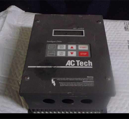
I've also had good luck with AC Tech drives. They are simple to program and are "value priced". I think you get more bang for your buck with these.

#40
Doesn't mcmaster offer Free PLC Software when you buy there PLC's? I'm forgetting which brand they push, but I seem to remember the "buy a PLC and get the software with it" package. I could be wrong, they may have changed it since I looked last.

#41
There's plenty of information in the other MPA drive post but I actually have written a simple setup procedure for how I would do it.

So if you have a bad drive and you are replacing it and would like to setup the new drive, this is what I do:


  • Remove the cover and duplicate the jumper settings on the new amp to match the old amp
  • Set the trim pots to match the old amp (I drew diagrams of the old amp jumpers, dip switches, and trim pots included below).
  • Disconnect COM+ and COM- command signal wires
  • Adjust the balance pot with a small screwdriver to eliminate any drifting of the motor (by the way, if safety is a concern you should disconnect the load from the motor in case the motor spins unexpectedly)
  • With those steps complete, you may be able to run your equipment normally and monitor with an o-scope for overshoot using the VELOCITY and GND test points
  • Connecting an o-scope to the CURRENT and GND test points displays the actual current at the instant of motion and may also provide you with some valuable info regarding the drive setup

The initial startup guide in the manual is also good but what I have learned is that you get better results faster when you simply match up the new and old drives exactly first, then go from there with fine tuning.
#42
Here's more info on the MTS MPA drives that is helpful. The startup procedure in the manual is very brief, it seems like you are assumed to know alot about drive setup and startup.

Here's what they have in the manual regarding startup:

Start-Up
Once normal wiring is verified, power can be applied to the amplifier.

Assure the DIP switch and jumpers are set as required. Default settings are for 6 pole motors on most MPA amplifiers; 4 pole motors on the MPA-05. Inputs Reset, +Limit, and -Limit are not going to disable the amplifier if they are not connected.

Never change the settings of DIP switch 2 with power ON.

The CUR and RESP adjustments are turned down (CCW). CUR is 50% and RESP is minimal.
It is recommended that CUR be turned to its full CCW position. Once power is applied, CUR can be slowly increased in a CW direction to achieve shaft torque. Crispness can be increased by a CW adjustment of RESP.

For start-up verification of wiring with external position controls the following simple test can be used to verify the phase relationship.

With the current limit turned full CCW or with the RST wiring disconnected, a CW rotation of the motor shaft will produce a negative command voltage at pin #9 (SIG) to pin #11 (GND) on the I/O (J1) connector. For a CCW rotation, a positive command must occur.

The rotation is started from a null, or a close to zero shaft position. If the relationship is wrong, there are two choices: interchange the A, A\ and B, B\ signals at the simulated encoder.
use the command - input for signal and pin #11 is still ground.

Either method works, but the first method still assures that positive command voltages cause CW rotation of the motor shaft as viewed from the shaft end of the motor.

Good Luck with your drive setup, hope this helps you out!
#43
As a note, we had issues with tuning on one of our drives and we fixed using external inductors that were supplied by MTS. External inductors were recommended from the beginning of the project and we decided to forgo them at first. We ended up adding them into the application eventually.

This is the section regarding external inductors that are optional to the MTS MPA drives.

External Inductors

External inductors can be placed in the amplifier R, S and T leads to assure that the minimum inductance specification is assured. The MPA-05/09/15 models all have 2mH drum core inductors installed under the top cover. These versions do not need external inductors to protect the motor. For the MPA-24/35/50/75/100 models, the inductance line-to-line must be no less than 4mH.

One inductor in each line is typical. The turn ON times of the power switches can cause catastrophic destruction of motors. Inductors in RST of the motor leads limit the rise time and preserve the motor.

All 460 volt motors should have inductors. Since the inductors can become very hot, it is recommended that they be wired external to the amplifier enclosure.

#44
This is information relating to the setup of the drive. The procedure from the manual isn't the greatest but this is what they have.

Set-Up

This procedure assumes that the amplifier is being used in the velocity mode otherwise the external controller would resolve PID gains for the amplifier and the amplifier would be in the TORQUE mode.

The USER adjustments are set as follows for shipping:


  • LEAD- Full CCW (no lead)
  • SIG - MID
  • RESP - MID
  • CUR - MID
  • BAL - MID


The procedure that is used to determine the actual SWITCH settings and USER adjustments is load and application dependent.

The best method to determine these is based on testing with Voltmeters and Oscilloscope for observing the TAG and command signal. P (proportional gain) is determined by the TAG and signal gains.

An oscilloscope can be used to monitor the TAG signal for over or under damping. The I (integral gain) is controlled by the RESP pot and the jumper settings of JL1 and JL2. The D (derivative gain) is determined by the adjustment of the LEAD pot.

An abbreviated method that allows for reasonable success is:


  • Determine the TAG gain for the application and set the JG1, 2, 3, and 4 jumpers accordingly. Amplifier saturation is based on 10 volts of either signal or TAG. With the TAG jumpers set for normal operation, the TAG gradient is 2.7 volts per thousand and saturation will occur at 10 volts max / 2.7 volts per Krpm = 3.7 Krpm. The motor's KE, and the amplifier's bus voltage will also limit the maximum speed.

    The amount of TAG gain alters the drive's proportional gain, and under most conditions higher TAG gains allow control of larger inertia. Since TAG gain compared to signal gain also controls velocity, the external controller's dc voltage proportional to velocity is an issue to consider. In some controllers a KF (feedforward term) is available. This term is a pre-computed voltage that is the velocity component.

    The controller's KP term adds or subtracts from this existing KF term, based on encoder count error, a voltage that forces correction. For this type of controller, the best possible performance can be achieved by having high TAG gain and minimum KP. Following errors are adjusted out with the drive's SIG adjustment when running at a known speed, and the BAL adjustment can be used to zero following error at zero velocity.

    Some controllers have no KF term and run error loops. Motion occurs as a result of the error over time, and for each time interval more error occurs causing higher speed. For this type of control, high TAG gains would generally deteriorate performance as the key to running is to make the same following errors at the same times.

    This type of control is very common. In several instances the difficulty in setup is that the external controller has no KP or KF term and the drive's KP is the only way of achieving stability. The drive's KP is determined by the TAG gain, SIG/AUX pot, LEAD pot. The best process would be to start out with the lowest TAG gain. Adjustment of the SIG/AUX input, RESP, and LEAD should cause normal operation.
  • The TAG filter jumper JF1 is usually IN (maximum filter). Removing JF1 decreases the filtering and is primarily intended to accommodate the brushless TAG option. In very fast applications, removing JF1 can improve bandwidth, but it depends on load conditions and various sized motors.
    Reducing filtering also leads to more audible noise. JL1 and JL2 should be IN for maximum integration, (I)
  • We would next set the RESP and CUR pots full CCW and assure that the
    LEAD pot is full CCW. The BAL pot and SIG pot are in the MID.
  • Power up the amplifier.
  • Slowly turn the CUR pot towards the middle position while observing the
    following.
    a. it may be necessary to increase the RESP adjustment to achieve
    stability or to minimize oscillation or vibration.
    b. if the instability is substantially improved but not good enough, the
    LEAD adjustment can be increased.
  • If operation is improved but not good enough, the process can be repeated
    from Step 3 after removing JL1. This decreases integration.
  • If operation is again improved but still not good enough, the process can be
    repeated from Step 3 after removing JL2. This increases gain.
  • If you are unable to achieve the speed you want, you may have to increase
    the SIG pot to have an 8-10 volt command signal equal the amplifiers
    maximum velocity.
  • You can also continue to increase the CUR adjust as operation is improved.


#45
Here is more info that relates to the wiring an IO details. I will post the drive setup information later due to time constraints but this should be a big help if you are configuring one of the MTS drives from scratch.


Simulated Encoder Signals

For external counting or position control, a 9-pin D type female connector that has TTL complimentary outputs is provided. This simulates quadrature encoder channel A and channel B signals. A differential mark signal is also available.

These signals are RS422 compatible. There are two jumpers that determine the resolution of the simulated encoder signals (JP1 and JP2). The normal factory configuration of 2-Channel quadrature provides for output resolution of 12 bits or 4096 counts per revolution. 14 bit resolution can be ordered by specifying a "-14" after the selected MPA amplifier (eg. MPA-09-460-14). With the "-14" option, the jumper configurations are as follows. The maximum 2-Channel resolution with quadrature channels in this mode is 16,384. The maximum tracking rate of the amplifier is limited to 60 rps or 3600 rpm with the "-14" option.

SIMULATED ENCODER

DIP switch S3 switches 1,2,3, and 4, are used for this purpose. By setting switch 2 to the OFF position, the operation of the + LIMIT would change to be closed to run in a plus direction. This reversing characteristic is true for all four switches.

There is a FAULT output. This is equivalent to an open collector NPN transistor with its emitter connected to GND. This transistor can sink 2 amps and it can withstand 110 volts dc when OFF. When a fault occurs, this output turns ON.

This output can also have its polarity inverted by switching the fourth switch on DIP switch S2. Once this is done, this output will be ON if no fault exists. This output would now be thought of as a READY output instead of a FAULT output.

The normal fault operation occurs with S2-4 ON. The purpose of inversion of this output is to allow for direct connection to fail safe brakes or other brake interlock circuits.

If this inverted output is used, consideration for the Power-Up Reset Input may be required. For example, during power-up a reset would disable faults. This same reset may then defeat the desired operation of the brake.

With no faults and an inverted output selected, the brake output would be ON but power would not be applied to the motor. If the JR1 shorting pin is installed then a Reset/Disable condition is allowed to keep the output ON even though there is no fault.

I/O Wiring and Descriptions

The amplifier has four inputs and one output. These inputs and output are designed to interface to a 24 volt logic system. The amplifier is shipped so that the operation of the inputs is as follows.


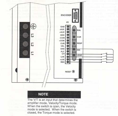
With no wires connected to RESET, + LIMIT, - LIMIT, or VELATORQUE, the amplifier is enabled and normal operation will occur in a velocity mode. The inputs are activated by connecting them with a switch closure to any of the provided GND terminals.

The VAT is an input that determines the amplifier mode, Velocity/Torque mode. When the switch is open, the Velocity mode is selected. When the switch is closed, the Torque mode is selected.
As the polarity of the inputs may vary depending on the application, a DIP switch is provided to allow for an inversion of the function.

Resolver Converter Resolution

These jumpers determine the 12 or 14-bit mode. Unless specified, all amplifiers are preset for 12-bit mode. JSC1 and JSC2 determine the R-Digital resolution. JB1 and JB2 determine the origin of the signals for the encoder simulation; When they are DOWN (2-3), the encoder simulation is based on the two LSD's of the 14 bit mode.

The encoder simulation jumpers JP1 and JP2 must also be IN. The line resolution is fixed at 4096 lines per channel. With the JB1 and JB2 jumpers in the UP (1-2) position, the two LSD's from the 12 bit mode are used for the encoder simulation and the JP1 and JP2 jumpers are used to alter the choices of the 12 bit mode.

When the R-D converter is configured for 14 bit mode, JB1 and JB2 can be placed in the UP (1 -2) position to allow for other encoder selection besides the normal 4096 lines per channel. Changing to 14-bit mode cannot be accomplished as a user option on a standard amplifier. The -14 option must be provided.

Analog Inputs, Outputs and Adjustments

Inputs: There are two analog input channels; one for command and one for auxiliary. Both of these channels are differential inputs and both are summed with a TAG feedback differential amplifier that controls velocity.

Normal operation of the command signal is to apply a + voltage (pin #9) with respect to GND(pin #11) and get clockwise rotation of the shaft. ±10 volts is then used to control velocity and the SIG pot is used for velocity adjustments. If the + COMMAND voltage is applied to the - COMMAND signal input, then an opposite shaft rotation occurs.

The operation of the AUXILIARY ± inputs is the same as the COMMAND inputs. The normal purpose of the AUXILIARY inputs is to provide a second summing voltage to compensate/modify normal COMMAND voltage.

If the input for VEL/TORQUE is active and a torque mode is chosen then voltages applied to the COMMAND ± inputs control motor current. The SIG pot can now be used to adjust the amount. Normal operation in this mode assumes that 10 voits is peak current and 5 volts is the continuous current rating of the amplifier.

The current limit of the amplifier can be adjusted with the CUR pot from 0 (full CCW) to 100% (peak full CW). It is a good idea during start-up to adjust the CUR pot to its full CCW position and increase it slowly CW to assure normal operation.

During start-up the BAL adjustment can be used to reduce/stop any low speed CW/CCW drift caused by imbalance between the external command voltage and the amplifier.

Once connected to loads, the crispness of motion (step response) and stability can be optimized with the RESP and LEAD pots. Full CW is maximum response and full CCW is minimum LEAD. The location of these adjustments is next to the I/O wiring.

Outputs: Two diagnostic outputs are the dc voltage proportional to velocity and the dc output proportional to current/torque. The nominal TAG gradient is 1.3 volts per thousand rpm. The current gradient is 10 volts equal peak.

Analog Inputs and Specific Interface Requirements

The analog input channels consist of differential input amplifiers to allow controllers that have differential output drivers a three wire connection that excludes potential ground loops. When differential modes of operation are used, the command or auxiliary input is based on 5 volts equaling maximum input and the analog ground from the external controller must be connected to the MPA drives GND connection.

A +5 volt connection to the COM+ terminal and a -5 volt connection to the COM- terminal is equal to a + 10 volts command voltage. The rotational direction of the motor will be CW viewed from the shaft end of the motor. To change directional rotation the COM+ and COM- connections must be reversed.

The most typical input to the command and auxiliary inputs is a simple two wire interface consisting of a command voltage with respect to a GND. The ground wire of this pair must be connected to the MPA GND terminal associated with the analog channel, and the command wire can be connected to either the COM+ or COM- input to determine the rotational characteristic required.

A positive command voltage with respect to GND connected to the COM+ terminal will cause CW rotation as viewed from the shaft end of the motor. The unused input, COM+ or COM-, should be connected to GND.

TAG Gradient, Response, Lead

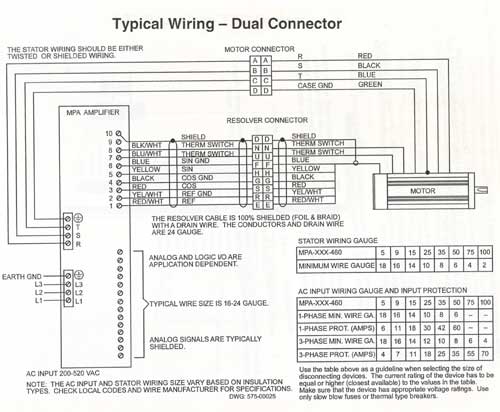
The control board for these amplifiers has jumpers that allow for various configurations of compensation and filter networks. The physical location of these jumpers is indicated on this figure.

Jumper Configurations

Lag Network-JL1  JL2: The JL1, JL2 jumpers and the (RESP) pot adjustment affect operation of the PID Loop's Term. The JL1 jumper varies the integration capacitor. The JL2 jumper varies the integration resistor.

The maximum integration occurs with the RESP pot full CCW. CW adjustment decreases integration, usually to a point of not being stable.

The maximum tracking rate of the resolver to digital converter in the 12-bit mode is 200 rps and is 60 rps in the 14-bit mode.

TACFilter-JF1: With JF1 IN the TAC filter is maximum and with it OUT the TAC filter is minimum. For smaller motors minimal TAC filtering improves response.


#46
I've compiled some information from the manual here. This may help you with the setup and troubleshooting of your drive.


Introduction:

QuoteMPA Amplifiers represent a series of amplifiers that are high performance, reliable, and efficient. The amplifiers are designed to be used with high performance brushless servo motors.  Extreme care has been taken to assure robust operation. Design consideration for electrical transients have been implemented on the ac inputs and all I/O lines.

MPA amplifiers operate over ac voltage ranges of 200 to 520 Vac from 45 to 65 Hz. The motor feedback device is a resolver to assure normal operation at elevated motor temperatures of 115° C for the case, and 155° C for the motor windings.

The resolver allows for both position and velocity feedback. The motor is further protected by a thermal shutdown thermostat in the motor windings. The amplifier high power switching devices are state of the art IGBT modules. The logic supplies are switch mode designs reducing undesired heat. LED indicators for diagnostics are provided.

Encoder simulated TTL compatible differential quadrature outputs plus an index output are provided for external pulse or position control. The amplifiers have inrush current protection to allow for normal turn on. This is especially worthwhile for multiple-axis applications. Consideration for dissipation of regenerative energy is included with internal shunt regulators.

Feedback Wiring:

100% shielded cable is foil and braid. The pairs do not have to be twisted. The resolver wiring should not be run adjacent to any non-shielded high voltage wires, such as the motor wires (RST). If the wiring cannot be separated, the RST motor leads should also be 100% shielded. It is highly recommended that factory cable sets or wiring be provided.

Thermostat:

If the motor is equipped with a winding thermostat that is normally closed, it can be connected between terminals 7 and 8 of the feedback wiring connector. If an excess temperature thermal condition exists as indicated by an open thermostat, the amplifier is disabled.

Motors and Commutation:

The amplifier can commutate 4-pole, 6-pole, 8-pole, and brush motors in its standard configuration and other factory options are available. DIP switch S2 allows for configuration changes and switches one and two determine the choice. Amplifiers are shipped set for 6-pole operation. Never change the switch settings of S2 with power ON.

All MTS Automation two-inch motors are 4-pole. The three-inch, four-inch, six-inch, and eight-inch motors are 6-pole motors. For brush motor operation, no resolver alignment is required and the R lead connects to armature (+) and the T lead connects to armature (-). These connections will cause clockwise rotation from the shaft end of the motor.

Diagnostic Indicators

Mark (RED): This is an output that comes ON at the resolver zero position and can be used in conjunction with alignment procedures. The zero position is about .5 degrees.

Current (BI-COLOR): This is a bi-color LED that can be either red or green as a function of load. Red indicates positive torque and green indicates negative torque. The intensity increases with load.

Power (GREEN): If logic +5 Vdc is ON, then this LED is ON.


Fault Analysis:

There are eight faults that will disable the amplifier, they are indiciated by LED:

CONTINUOUS - If a load condition exists that causes the amplifier to produce more than its continuous rating, this fault occurs.

STATOR SHORTS - If stator shorts or most major wiring errors of the stator occur, this fault occurs.

AMPLIFIER THERMAL - An 85° C thermostat is mounted to the amplifier's IGBT heat sink. If an excess temperature is sensed, this fault occurs.

FEEDBACK WIRING - For most resolver wiring errors, defective resolvers or tracking rate errors caused by the resolver, this fault occurs.

MOTOR THERMAL or OVERSPEED - If an excess thermal or adjustable condition exists in the motor, this fault occurs.

HI-BUS - If excess DC voltage or a failure of the shunt circuit occurs, this fault occurs.

RESET - During the first second of power up or if the reset input is active, this LED will be ON.

LIMIT - If either of the limit inputs are ON, This LED will be ON.
#47
As for the Yaskawa overcurrent fault,  here are the suggestions form the manual. There are quite a few things you can check.


  • The motor has been damaged due to overheating or the motor insulation is damaged.
    You should check the insulation resistance or replace the motor.
  • One of the motor cables has shorted out or there is a grounding problem. You should check the motor cables and remove the short circuit and power the drive back up.
  • The load is too heavy. Things to try, you should: Measure the current flowing into the motor,
    replace the drive with a larger capacity unit if the current value exceeds the rated current of the drive, determine if there is sudden fluctuation in the current level, and reduce the load to avoid sudden changes in the current level or switch to a larger drive.
  • The acceleration or deceleration times are too short. You should: Calculate the torque needed during acceleration relative to the load inertia and the specified acceleration time. If the right amount of torque cannot be set, make the following changes: Increase the acceleration time (C 1-01,C1-03), Increase the S-curve characteristics (C2-01 through C2-04), or Increase the capacity of the drive.
  • The drive is attempting to operate a specialized motor or a motor larger than the maximum size allowed. You should: Check the motor capacity. Ensure that the rated capacity of the drive is greater than or equal to the capacity rating found on the motor nameplate.
  • Magnetic contactor (MC) on the output side of the drive has turned on or off. You should: Set up the operation sequence so that the MC is not tripped while the drive is outputting current.
  • V/f setting is not operating as expected. You should: Check the ratios between the voltage and frequency, set parameters El-04 through El-10 appropriately. Also lower the voltage if it is too high relative to the frequency.
  • Excessive torque compensation. You should: Check the amount of torque compensation and reduce the torque compensation gain (C4-01) until there is no speed loss and less current.
  • Drive fails to operate properly due to noise interference. You should: Review the possible solutions provided for handling noise interference. Review the section on handling noise interference and check control circuit lines, main circuit lines, and your grounding.
  • Over-excitation gain is set too high. You should: Check if fault occurs simultaneously to over-excitation function operation and consider motor flux saturation and reduce the value of n3-13 (Overexcitation Deceleration Gain).
  • Run command applied while motor was coasting. You should: Program the Speed Search command input through one of the multi-function contact input terminals (Hl-DD = 61 or 62).
  • The motor cable is too long.  You should use a larger drive to reduce overcurrent.

#48
Here is a Yaskawa Fault list that I have. I just put the fault code and an indication of what each fault actually is.


  • oL3 - Overtorque 1 Details: Drive output current was greater than the value set at L6-02 for longer than the time set at L6-03
  • ou - DC Bus Overvoltage Details: The DC bus has exceeded the trip point
  • CE - Modbus or memobus communication error since no data was received for longer than 2 secondsDetails:
  • CoF - Current Offset Fault Details: The current sensor is damaged or there was some residual induction current in the motor (possible sudden deceleration or it was still coasting) when the drive tried to start the motor
  • CPF00 - RAM, ROM, or CPU Fault Details: CPF11 is Ram Fault, CPF12 is ROM Fault (flash memory), CPF14 is CPU error, CPF17 is a timing error, CPF18 is a CPU error
  • CPF01 - RAM, ROM, or CPU Fault Details: CPF11 is Ram Fault, CPF12 is ROM Fault (flash memory), CPF14 is CPU error, CPF17 is a timing error, CPF18 is a CPU error
  • CPF02 - Analog/Digital conversion error Details: because an error relating to A/D conversion has occurred
  • CPF06 - EEPROM Data errorDetails: There is an error in the data saved to eeprom
  • CPF08 - EEPROM Serial Communication faultDetails: The EEPROM communications are not operating properly
  • CPF20 - RAM Fault / ROM Fault / Watchdog Error / Clock ErrorDetails: One of these faults occurred, a RAM fault, a ROM Fault, Flash Error, watchdog circuit error, or clock error
  • CPF21 - RAM Fault / ROM Fault / Watchdog Error / Clock Error Details: One of these faults occurred, a RAM fault, a ROM Fault, Flash Error, watchdog circuit error, or clock error
  • CPF22 - A/D Conversion Fault Details: Thi is a A/D conversion error message
  • CPF23 - PWM Feedback Fault Details: This is a PWM Feedback Error
  • CPF24 - Drive capacity signal fault Details: The drive enetered a capacity that doesn't exist
  • EFO - MEMOBUS/Modbus communications external fault Details: An external fault was present
  • EF1 - External Fault Details: External Fault on input terminal S1
  • EF2 - External Fault Details: External Fault on input terminal S2
  • EF3 - External Fault Details: External Fault on input terminal S3
  • EF4 - External Fault Details: External Fault on input terminal S4
  • EF5 - External Fault Details: External Fault on input terminal S5
  • Err - EEPROM Write Error Details: Does not match the EEPROM it is being written to
  • LF -  Output Phase Loss Details: There is a phase loss on the output side of the drive
  • oC - Overcurrent Details: Drive sensors have detected an output current greater than the specified overcurrent level
  • oFAO1 - Option Unit Fault Details:You have to replace the option unit
  • oH1 - Overheat 1 (heatsink Overheat) Details: The temperature on the heatsink has exceeded the overheat pre-alarm level
  • oL1 - Motor Overload Details: The electro-thermal sensor tripped overload protection
  • oL2 - Drive Overload Details: The thermal sensor of the drive triggered overload protection
  • oL3 - Overtotque Protection 1 Details: The current has exceeded the value set for torque detection L6-02 for longer than the allowable time
  • oPr - External Digital Operator Connection Fault Details: The external operator has been disconnected from the drive
  • ou - Overvoltage Details: Overvoltage on the DC bus has exceeded the overvoltage detection level
  • PF - Input Phase Loss Details: Drive input power has an open phase or a large imbalance of voltage between phases
  • rH - Braking Resistor Overheat Details: Braking resistor protection was triggered
  • Uu1 - DC Bus Undervoltage Details: Voltage on the DC bus has fallen below the undervoltage detection level
  • Uu3 - Undervoltage 3 Inrush Prevention Circuit Fault Details: The inrush prevention circuit has failed
  • bb - Baseblock Details: The drive output is interrupted as indicated by an external baseblock signal
  • CALL - Serial Communication Transmission Error Details: Communication hasn't been established
  • CE - MEMOBUS/Modbus Communication ErrorDetails: Control data wasn't received correctly for two seconds
  • CrSr - Can't Reset (CrST) Details: Fault reset was executed when the run command was entered
  • EF - Forward/Reverse Run Command Input Error Details:Both forward and reverse run closed simultaneously for at leat .5 seconds
  • oH - Heatsink Overheating Details: The heatsink temperature exceede the temperature setting
  • PASS - MEMOBUS/Modbus Test Details: The memobus/modbus test mode is complete
  • SE - MEMOBUS/Modbus Error Details: There is a MEMObus/MODbus test mode error
  • Uu - Undervoltage Details: DC bus voltage dropped below the undervoltage detection level
#49
Yes oC is overcurrent, Yaskawa says that the drive sensors have detected an output current that is higher than specified in your parameters.

oH is Heatsink, the operating temperature has exceeded the parameter value set to L8-02.

I'll list a more inclusive Yaskawa Fault list shortly and i'll include some of the suggestions for clearing the faults/alarms.
#50
First off, do you get a fault, an alarm, or an operational error? These are the explanations for Yaskawa...

Yaskawa Faults:
When the drive detects a fault:
The digital operator displays text that indicates the specific fault and the ALM indicator LED
remains lit until the fault is reset. The fault interrupts drive output and the motor coasts to a stop.
Depending on the setting, the drive and motor may stop via different methods than listed.


Yaskawa Minor Faults and Alarms:
When the drive detects an alarm or a minor fault: The digital operator displays text that indicates the specific alarm or minor fault and the ALM indicator LED flashes. The motor won't stop.

The multi-function contact output closes if set to be tripped by a minor fault (H2-01 = 10), but
not by an alarm. The digital operator displays text indicating a specific alarm and ALM indicator LED flashes. Remove the cause of an alarm or minor fault to automatically reset.

Yaskawa Operation Errors:
When parameter settings conflict with one another or do not match hardware settings (such as with an option unit), it causes an operation error. When the drive detects an operation error:
The digital operator displays text that indicates the specific error. The multi-function contact output does not operate. When the drive detects an operation error, it will not operate the motor until the error has been reset. Correct the settings that caused the operation error to reset.


#51
The Maintenance Saloon / Re: Yaskawa Drive Reviews
February 02, 2017, 04:25:AM
I have experience with numerous Yaskawa drives and have found them fairly easy to set up. Once you have done a few you get familiar with their menu system and calibrating becomes easier. Haven't had any issue with drive failures. Sometimes it feels like the plastic housing on the drives could be more stout, that would be my only complaint.
#52
Hello,
I have worked with a few different Yaskawa AC drives. I have worked with 2nd level engineering on three projects so far and my role included setup and optimization of yaskawa drives on motors that were 1 HP or less.

They make a few different AC drives, which series did you have problems with?


  • Yaskawa A1000: General Purpose
  • Yaskawa P1000: Fans and Pumps
  • Yaskawa U1000: Industrial Matrix Drive
  • Yaskawa V1000: Compact Vector
  • Yaskawa J1000: Ultra Compact