- Welcome to OI Roundtable.


The Maintenance Technicians App
Recent posts
#1
Electrical and Electronic / Re: 1606XL Power Supply Proble...
Last post by Cheller - April 30, 2024, 04:40:AMYou 'gotta be more specific than that.
#2
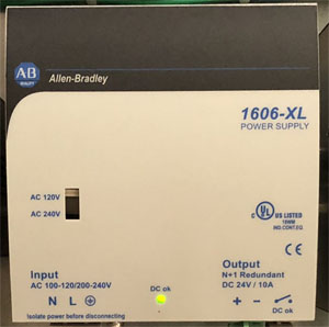
Electrical and Electronic / 1606XL Power Supply Problems
Last post by brianc75 - April 29, 2024, 04:13:AMAnyone ever have nagging problems with 1606XL power supplies from Allen Bradley. Not sure if it's my application, or if these are problematic.
#3
Electrical and Electronic / Re: Parker DC590+ DRV Troubles...
Last post by benklassne - April 28, 2024, 04:37:AM
#4
Troubleshooting 101 / WEG CFW09 Faults - CFW-09 Driv...
Last post by zigmund - April 28, 2024, 04:19:AMHere is the listing of Weg CFW-09 faults. This list is really helpful for CFW09 troubleshooting and there are brief explanations for the faults included. When a fault is detected, the inverter is disabled and the Fault Code is
displayed on the readout in the EXX form, where XX is the actual fault number, for example: E01.
To restart the inverter after a fault has occurred, the inverter must be reset. You can reset the drive by: disconnecting and reapplying AC power (which is power-on reset), by pressing the key (manual reset), automatic reset through P206 (auto-reset setting), by digital input: DIx = 12 (P265 to P270 also found in settings), by Serial interface, or by Fieldbus interface. Here is the list of CFW09 alarms / faults:
- E00 Output Overcurrent :: Causes: Short-circuit between two motor phases, Short-circuit between braking resistor cables, When the output current reaches 2 x P295, caused by: very high
DIx (Digital Input) load inertia, acceleration ramp too fast or incorrect regulation and / or configuration parameters, Transistor module shorted, or P169 to P172 set too high - E01 Overvoltage (Ud) :: Causes: Power Supply voltage too high, check Ud in P004: 220-230 V Models - Ud > 400 V, 380-480 V Models - Ud > 800 V, 500-600 V and 500-690 V Models with power supply between
500 V and 600 V - Ud > 1000 V, 500-690 V models with power supply between 660 V and 690 V and 660-690 V models - Ud > 1200 V, Load inertia too high or deceleration ramp too short, or P151 or P153 set too high - E02 Undervoltage (Ud) :: Causes: Power Supply voltage too low, DC Link check Ud in P004: 220-230 V power supply - Ud < 223 V, 380 V power supply - Ud < 385 V, 400-415 V power supply - Ud < 405 V, 440-460 V power supply - Ud < 446 V, 480 V power supply - Ud < 487 V, 500-525 V power supply - Ud < 532 V, 550-575 V power supply - Ud < 582 V, 600 V power supply - Ud < 608 V, 660-690 V power supply - Ud < 699 V, Phase loss at the input, Auxiliary circuit fuse blown (only valid for 105 A and 130 A/220-230 V, 86 A to 600 A/380-480 V and 44 A to 79 A/500-600 V refer to item 3.2.3), Pre-charge contactor defective, P296 set to a voltage higher than the power supply voltage
- E03 Input Undervoltage / Phase loss :: Causes: Power Supply voltage is too low, check Power Supply voltage: 220-230 V Models - Power Supply < 154 V, 380-480 V Models - Power Supply < 266 V, 500-600 V and 500-690 V Models - Power Supply < 361 V, 660-690 V Models - Power Supply < 462 V, Phase loss at the inverter input, Activation Time: 2.0 s
- E04 Inverter Overtemperature or Pre-Charge Circuit Defective :: Causes: Ambient temperature too high (> 40 degree C) and/or output current too high; or ambient temperature < -10 degree C, Blowers locked or defective, Auxiliary circuit fuse blown (only valid for 105 A and 130 A/220-230 V, 86 A to 600 A/380-480 V and 44 A to 79 A/500-600 V refer to item 3.2.3), Problem with the supply voltage - voltage sag or interruption (phase loss) - last for more than 2 seconds and with the phase loss detection disabled (P214 = 0), Signal with inverted Polarity at Analog inputs AI1/AI2
- E05 Inverter Motor / Overload (i x t function) :: Causes: P156, P157 and P158 set too low for the motor being used, Motor is under an actual overload condition
- E06 External Fault :: Causes: Any DIx (DI3 to DI7) programmed for external fault detection (P265 to P270 set to 4 – No Ext Flt) is open (not connected to + 24 V), Terminal block XC12 on the control board CC9 is not properly connected
- E07 Encoder Fault :: Causes: Miswiring between encoder and terminal block XC9 (optional board Encoder Fault EBA/EBB/EBC/EBE). Refer to item 8.2, Encoder is defective
- E08 CPU Error :: Causes: Electrical noise
- E09 Program Memory Error (Checksum) :: Causes: Memory with corrupted values
- E10 Error in the Copy Function :: Causes: A bid to copy the HMI parameters to the inverter with different Software Version
- E11 Ground Fault :: Causes: Short-circuit between one or more output phases and ground, Motor cable capacitance to ground is too high
- E12 Braking Resistor Overload :: Causes: Load inertia too high or deceleration ramp too short, Load on the motor shaft too high, P154 and P155 programmed incorrectly
- E13 Incorrect Encoder Sense of Direction :: Causes: Cables U, V, W to motor are inverted, Encoder channels A and B are inverted, Encoder mounted in wrong position. Quick Note: This fault will only occur during self-tuning
- E15 Motor Phase Loss :: Causes: Bad contact or broken wiring between motor and inverter, Incorrect value programmed in P401, Vector Control without orientation, Vector Control with encoder, encoder wiring or connection to motor is inverted
- E17 Overspeed Fault :: Causes: When the effective overspeed exceeds the value of P134+P132 longer than 20ms
- E24 Programming Error :: Causes: Incompatible parameters were programmed.
- E31 Keypad (HMI) Connection Fault :: Causes: Keypad cable misconnected, Electrical noise in the installation (electromagnetic interference)
- E32 Motor Overtemperature :: Causes: Motor is under an actual overload condition, Duty cycle is too high (too many starts/stops per minute), Ambient temperature is too high, Motor thermistor miswiring or short-circuit (resistance < 100 ?) at the terminals XC4:2 and XC4:3 of the optional board EBA or at the terminals XC5:2 and XC5:3 of the optional board EBB, P270 programmed to 16 unintentionally, with EBA/EBB board not installed and/or motor thermistor not connected, Motor in locked rotor condition
- E33 Speed Without Control :: Causes: Overweight, Brake Failure
- E34 Long Period at Torque Limit :: Causes: The load was too heavy and the CFW-09 operated at torque limitation, for a period longer than allowed, Failure on the brake opening caused the CFW-09 to operate at torque limitation for a period longer than allowed
- E41 Self Diagnosis Fault :: Causes: Memory error or any internal inverter circuit defective
- E70 Internal DC Supply Undervoltage :: Causes: Phase loss at the R or S input, Auxiliary circuit fuse blown (only valid for 500-690 V and 660-690 V models - refer to figures 3.7 f) and g))
- E71 Watchdog Error for the PLC Board :: Causes: When the PLC board stops communicating with the CFW-09 for more than 200 ms
#5
Troubleshooting 101 / Re: What is the easiest way to...
Last post by benklassne - April 26, 2024, 05:28:AMGood info, I thought it was worth bumping.
#6
Troubleshooting 101 / Re: Troubleshooting a Thermoco...
Last post by benklassne - April 26, 2024, 04:43:AMGood work on the thermocouple tests...
#7
Troubleshooting 101 / Re: What is the easiest way to...
Last post by benklassne - April 26, 2024, 04:38:AMNice job with the resolver testing. These are black boxes to a lot of people who just swap parts.
#8
Troubleshooting 101 / Re: Toshiba H9 Drive Alarms
Last post by benklassne - April 25, 2024, 04:24:AM
#9
Troubleshooting 101 / Re: Allen Bradley Power Flex A...
Last post by benklassne - April 25, 2024, 04:22:AM
#10
Troubleshooting 101 / Re: Toshiba VF-AS1 Alarms and ...
Last post by benklassne - April 25, 2024, 04:21:AM