News:

Obsolete industrial electronics forum is still alive and well, just undergoing some maintenance and more anti spam stuff, stand by for a better experience

Main Menu
Menu

Show posts

This section allows you to view all posts made by this member. Note that you can only see posts made in areas you currently have access to.

Show posts Menu

Topics - actionjack

#1
How to Measure lnverter Output Voltage

Taking voltage measurements around drives (frequency drives or inverters if you prefer) requires the right test equipment and some attention to detail. You will be working with high voltage and high-frequency switching waveforms that are not pure sine waves.

Digital voltmeters don't usually produce reliable readings for these waveforms since they are not purely sinusodial. And it is also risky to connect high voltage signals to oscilloscopes, so with these limitation in mind there is still a fairly easy method to measure inverter output voltage.

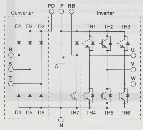
Since the inverter output semiconductors will most likely have some leakage, taking no-load measurements will produce misleading results.

So, you will need to assemble a circuit like the ones here to measure voltage when performing drive maintenance or troubleshooting. This procedure is adapted from one presented an old Hitachi drive manual.


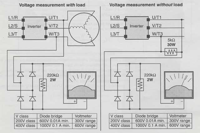
The testing circuits are assembled using common diodes and resistors.

You must use caution not to touch wiring or output terminals when working with the drive/inverter and taking these measurements.

Be sure to place the homemade testing circuits in an insulated housing before using them to avoid short circuiting or electrocution of the technician.
#2
Troubleshooting 101 / How to Test Drive IGBT
January 21, 2019, 05:05:AM
How to Test Drive IGBT

Here is the lGBT test method as it appeared in an older Hitachi drive manual... This is a great way to pinpoint the source of drive/motor issues.

The following procedure will check the inverter transistors (IGBTs) and diodes:

1. Disconnect input power to terminals [R, S, and T] and motor terminals [U, V, and W].

2. Disconnect any wires from terminals [P] and [RB] for regenerative braking.

3. Use a Digital Volt Meter (Multi-meter) and set it for 1 ohm resistance range. You can check the status of the charging state of terminals [R, S, T, U, V, W, RB, P, and N] of the inverter and the probe of the voltmeter by measuring the charging state.


If resulting reading is almost infinite ohms = "non-conducting," and readings from 0 to 10 ohms = "conducting."

NOTE 1: The resistance values for the diodes or the transistors will not be exactly the same, but they will be close. If you find a significance difference, a problem may exist.

NOTE 2: Before measuring the voltage between [P] and [N] with the DC current range, confirm that the smoothing capacitor is discharged fully, then execute the tests.


Good luck and Happy IGBT'ing


#3
Variable Frequency Inverters FAQ

Here are some Frequently Asked Questions from one of the Hitachi inverter manuals, they pertain to most brands and are pretty educational.


Q. What is the main advantage in using an inverter to drive a motor, compared to alternative solutions?

A. An inverter can vary the motor speed with very little energy loss, unlike mechanical or hydraulic speed control solutions. The resulting energy savings can often pay for the inverter in a relatively short time.


Q. The term "inverter" is a little confusing, since we also use "drive" and "amplifier" to describe the electronic unit that controls a motor. What does "inverter" mean?

A. The terms are used somewhat interchangeably in industry. Nowadays, the terms drive, variable-speed drive, variable freq drive, and inverter[i/] are used to describe electronic, microprocessor-based motor speed controllers. In the past, variable speed drive[i/] also referred to various mechanical means to vary speed. "Amplifier" is a term almost exclusively used to describe drives for servo or stepper motors.

Q. Can I use a variable speed drive for a fixed-speed application?

A. Yes, sometimes an inverter can be used simply as a "soft-start" device, providing controlled acceleration and deceleration to a fixed speed. Other functions of the inverter may be useful in such applications, as well. However, using a variable speed drive can benefit many types of industrial and commercial motor applications, by providing controlled acceleration and deceleration, high torque at low speeds, and energy savings over alternative solutions.


Q. Can I use an inverter and AC induction motor in a positioning application?

A. That depends on the required precision, and the slowest speed the motor must turn and still deliver torque. Some inverters deliver 200% rated torque while turning the motor at low speed. DO NOT use an inverter if you need the motor to stop and hold the load position without the aid of a mechanical brake (use a servo or step`per motion control system).

Q. Why does the manual or other documentation use terminology such as "200V class" instead of naming the actual voltage, such as "230 VAC?"

A. A specific inverter model is set at the factory to work across a voltage range particular to the destination country for that model. The model specifications are on the label on the side of the inverter. A European 200V class inverter ("EU" marking) has different parameter settings than a USA 200V class inverter ("US" marking).


Q. Why doesn't the motor have a neutral connection as a return to the inverter?

A. The motor theoretically represents a "balanced Y" load if all three stator windings have the same impedance. The Y connection allows each of the three wires to alternately serve as input or return on alternate half-cycles.


Q. Does the motor need a chassis ground connection?

A. Yes, for several reasons. Most importantly, this provides protection in the event of a short in the motor that puts a hazardous voltage on its housing. Secondly, motors exhibit leakage currents that increase with aging. Lastly, a grounded chassis generally emits less electrical noise than an ungrounded one.


Q. What type of motor is compatible with a variable freq inverter?

A. Motor type - It must be a three phase AC induction motor. Use an inverter-grade motor that has 800V insulation for 200V class inverters, or 1600V insulation for 400V class. Motor size -In practice, it's better to find the right size motor for your application; then look for the inverter to match the motor. NOTE: There may be other factors that will affect motor selection, including heat dissipation, motor operating speed profile, enclosure type, and cooling method.


Q. How many poles should the motor have?

A. Most inverters can be configured to operate motors with 2, 4, 6, or 8 poles. The greater the number of poles, the slower the top motor speed will be, but it will have higher torque at the base speed.


Q. Will I be able to add dynamic (resistive) braking to my inverter/drive after the initial installation?

A. Yes.  You can add an external resistor to some models to improve braking performance. Some require.you to add an external braking unit. The braking resistor connects to the external braking unit for those models.


Q. How will I know if my application will require resistive braking?

A. For new applications, it may be difficult to tell before you actually test a motor/drive solution. In general, some applications can rely on system losses such as friction to serve as the decelerating force, or otherwise can tolerate a long decel time. These applications will not need dynanic braking. However, applications with a combination of a high-inertia load and a required short decel time will need dynamic braking. This is a physics question that may be answered either empirically or through extensive calculations.


Q. Several options related to electrical noise suppression are available for variable speed inverters. How can I know if my application will require any of these options?

A. The purpose of these noise filters is to reduce the inverter electrical noise so the operation of nearby electrical devices is not affected. Some applications are governed by particular regulatory agencies, and noise suppression is mandatory. In those cases, the inverter must have the corresponding noise filter installed. Other applications may not need noise suppression, unless you notice electrical interference with the operation of other devices.


Q. PID loops are usually associated with chemical processes, heating, or process industries in general. How could the PID loop feature be useful in my application?

A. You will need to determine the particular main variable in your application the motor affects. That is the process variable (PV) for the motor. Over time, a faster motor speed will cause a faster change in the PV than a slow motor speed will. By using the PID loop feature, the inverter commands the motor to run at the optimal speed required to maintain the PV at the desired value for current conditions. Using the PID loop feature will require an additional sensor and other wiring, and is considered an advanced application.
#4
Can you use a 400V motor with 480V?

We are having a discussion at work about a used motor we have. It is rated at 400V 50HZ. We have incoming power of 480V 60HZ and we are debating whether or not it will last. Has anyone had experience using 400V motors on a 480V system?