News:

Obsolete industrial electronics forum is still alive and well, just undergoing some maintenance and more anti spam stuff, stand by for a better experience

Main Menu
Menu

Show posts

This section allows you to view all posts made by this member. Note that you can only see posts made in areas you currently have access to.

Show posts Menu

Messages - actionjack

#1
The Maintenance Saloon / Re: Hello from MidWest
February 26, 2022, 06:05:AM
If you're stuck with the sump pump, maybe you can at least make it more energy efficient?

How about adding an external float that's adjustable so the pump cycles less often?

Can you find a single phase soft starter to decrease your electricity cost and make the pump more energy efficient?

If you have to live with a water problem, maybe that would ease the pain. Good luck.
#2
That's a tough one, because application is everything. I like using a combination of dynamic braking with supplemental mechanical braking when the start and stop time is too intense for dynamic braking alone.

I really can't see why you would want to disable dynamic braking all together, anybody else??
#3
Electrical and Electronic / Re: What is Deadband?
February 18, 2019, 08:38:AM
Quote from: drodriquez on February 06, 2019, 07:38:AM
Can someone provide a textbook definition of deadband in relation to inverters and drives? What is deadband?

So, in a drive or any electronic control system, its the range of input change where there is no perceptible change to the output, almost like too small of a change to warrant a response.

Deadband may or may not be desirable; it depends on the design and the particular application.
#4
Electrical and Electronic / Re: What is Reactance
January 28, 2019, 04:22:AM
Quote from: drodriquez on January 22, 2019, 04:00:AM
Question: What is reactance in regards to drives and motors? What does "reactance" mean?

First impedance (of inductors and capacitors) has two components; the resistive part is constant,
while the reactive part changes with the current frequency.

Drives/inverters have a complex impedance, where the resistance is the real part (measurable)  and the reactance is the imaginary portion.

Hope that helps.
#5
Troubleshooting 101 / Re: What is Duty Cycle
January 28, 2019, 04:18:AM
Quote from: drodriquez on January 22, 2019, 03:58:AM
Question:  What is Duty Cycle in reference to AC and DC motors?

This is the percent of time a square wave of a fixed frequency is ON (high) versus OFF (low).

So the ratio of operating time of a motor, braking resistor, etc. to its resting time. These drive  parameters are usually is specified in association with the allowable thermal characteristics for the device.

In other words, it would be set to protect the motor and drive from overheating by working them too hard...
#6
This is just the torque a motor must produce to overcome the static friction of a load in order to start the load moving.

It makes more sense after you've heard the explanation.


#7
Pulse-width modulation is a type of AC variable frequency drive that accomplishes frequency
and voltage control at the output section (inverter) of the drive.

The drive output voltage waveform is at a constant amplitude, and by "chopping" the waveform (this is the pulse-width modulating), the average voltage is controlled.

The chopping frequency is sometimes called the carrier frequency. PWM drives are common but the PWM descriptor is assumed and many times not even mentioned.
#8
A line reactor is a three-phase inductor generally installed in the AC input circuit of a drive (inverter) to minimize harmonics and to limit short-circuit current.

They are sometimes sold as an accessory or reactor kit with the drive. As a matter of fact you'll find reactor kits available more often than not.
#9
4 Quadrant Operation is simply the way to refer to a graph of torque versus speed.

A 4 quadrant drive (inverter) can turn the motor either forward or reverse, as well as decelerate in either direction (in other words there are no limitations dependent on motor direction).

A load that has a high inertia and must move in both directions while changing directions rapidly requires four-quadrant capability from the drive.

There are many applications requiring four quadrant drives and they are pretty common.
#10
Auto-Tuning is the ability of a drive controller to execute a procedure that interacts with a motor load to determine the proper coefficients to use in the motor control algorithm and to determine motor parameters for optimal commutation.

Auto-tune makes the drive motor combo more efficient and basically mates the two together. If you replace the motor, you will need to auto-tune again, likewise if your drive gets replaced you'll need to perform an auto-tune when you are starting your initial setup.
#11
Troubleshooting 101 / Re: Thermal Switch Failure
January 21, 2019, 05:15:AM
Thermal switches are electro-mechanical safety devices that open to stop current flow when the temperature at the device reaches a specific temperature.

Thermal switches are sometimes installed in the motor in order to protect the windings from damage during over-temperature events. The drive (or inverter) will use thermal switch signals to trip (shut down) if the motor overheats.

So if your thermal switch is opening and there is no excessive overheating in the motor, your problem may be as simple as the interconnecting wires. Check your connections between the drive and motor.
#12
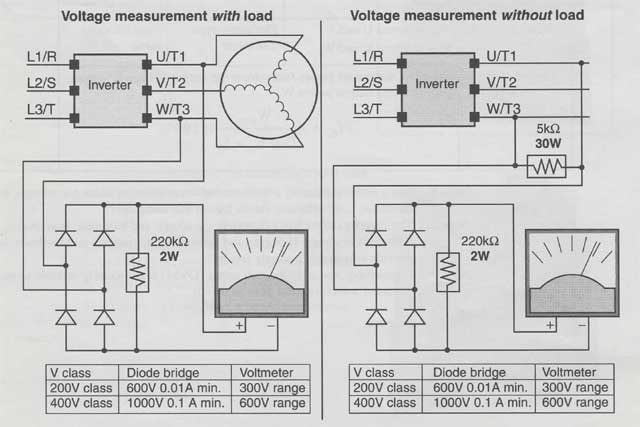
How to Measure lnverter Output Voltage

Taking voltage measurements around drives (frequency drives or inverters if you prefer) requires the right test equipment and some attention to detail. You will be working with high voltage and high-frequency switching waveforms that are not pure sine waves.

Digital voltmeters don't usually produce reliable readings for these waveforms since they are not purely sinusodial. And it is also risky to connect high voltage signals to oscilloscopes, so with these limitation in mind there is still a fairly easy method to measure inverter output voltage.

Since the inverter output semiconductors will most likely have some leakage, taking no-load measurements will produce misleading results.

So, you will need to assemble a circuit like the ones here to measure voltage when performing drive maintenance or troubleshooting. This procedure is adapted from one presented an old Hitachi drive manual.


The testing circuits are assembled using common diodes and resistors.

You must use caution not to touch wiring or output terminals when working with the drive/inverter and taking these measurements.

Be sure to place the homemade testing circuits in an insulated housing before using them to avoid short circuiting or electrocution of the technician.
#13
Troubleshooting 101 / How to Test Drive IGBT
January 21, 2019, 05:05:AM
How to Test Drive IGBT

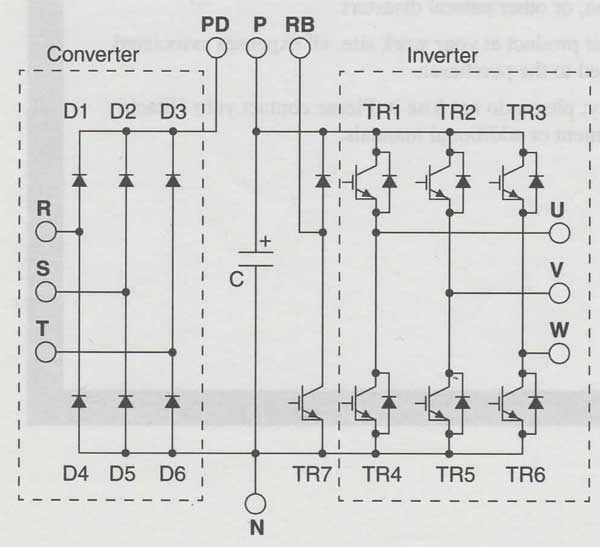
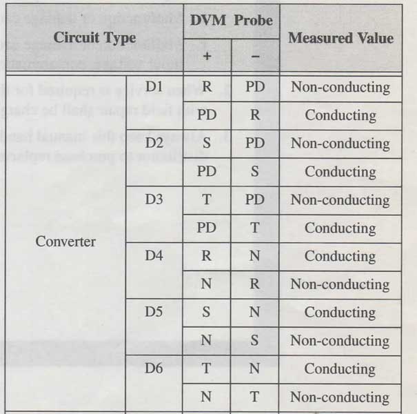
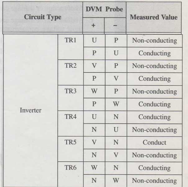
Here is the lGBT test method as it appeared in an older Hitachi drive manual... This is a great way to pinpoint the source of drive/motor issues.

The following procedure will check the inverter transistors (IGBTs) and diodes:

1. Disconnect input power to terminals [R, S, and T] and motor terminals [U, V, and W].

2. Disconnect any wires from terminals [P] and [RB] for regenerative braking.

3. Use a Digital Volt Meter (Multi-meter) and set it for 1 ohm resistance range. You can check the status of the charging state of terminals [R, S, T, U, V, W, RB, P, and N] of the inverter and the probe of the voltmeter by measuring the charging state.


If resulting reading is almost infinite ohms = "non-conducting," and readings from 0 to 10 ohms = "conducting."

NOTE 1: The resistance values for the diodes or the transistors will not be exactly the same, but they will be close. If you find a significance difference, a problem may exist.

NOTE 2: Before measuring the voltage between [P] and [N] with the DC current range, confirm that the smoothing capacitor is discharged fully, then execute the tests.


Good luck and Happy IGBT'ing


#14
Watt Loss is simply a measure of the internal power loss of a specific component, the difference between the power it consumes and the amount of power its output delivers.

An inverter/drive's watt loss is the input power minus the power delivered to the motor. The watt loss is typically highest when an inverter is delivering its max output. Therefore, watt loss is usually specified for specific output levels.

Inverter/drive watt loss specifications are important when designing enclosures mainly because of heat dissipation and overall power consumption.
#15
EMI is defined as Electromagnetic Interference

In motor/drive systems, the switching of high currents and voltages creates the possibility of generating some radiated electrical noise that can interfere with the operation of nearby sensitive electrical instruments or devices. Certain aspects of an installation, such as the long motor lead wire lengths, tend to increase the chance of experiencing EMI.

Most drive manufacturers produce accessories and filter components that you can install to decrease the level of EMI in your drive system.
#16
Motors can be confusing.... or not.

A stator is the name for the windings in a motor that are stationary and coupled to the power input of the motor. Just think stationary.

A rotor is the name for the windings of a motor that rotate, being physically coupled to the motor shaft. Just think rotating.


#17
Troubleshooting 101 / Re: ABB ACS Drive Fault List
January 19, 2019, 07:32:AM
ABB ACS 550 Fault and Alarm List

Just and FYI, ABB considers faults to be critical and alarms to be less severe so they are considered advisory.

Fault Number: 1 Fault name: OVERCURRENT Fault/Alarm Description: Output current is excessive. Check for and correct: Excessive motor load, Insufficient acceleration time (parameters 2202 ACCELER TIME 1 and 2205 ACCELER TIME 2), Faulty motor, motor cables or connections.

Fault Number: 2 Fault name: DC OVERVOLT Fault/Alarm Description: Intermediate circuit DC voltage is excessive. Check for and correct: Static or transient overvoltages in the input power supply, Insufficient deceleration time (parameters 2203 DECELER TIME 1 and 2206 DECELER TIME 2), Undersized brake chopper (if present).
• Verify that overvoltage controller is ON (using parameter 2005).

Fault Number: 3 Fault name: DEV OVERTEMP Fault/Alarm Description: Drive heatsink is overheated. Temperature is at or above limit. R1...R4: 115 °C (239 °F) R5, R6: 125 °C (257 °F) Check for and correct: Fan failure, Obstructions in the air flow, Dirt or dust coating on the heat sink, Excessive ambient temperature, Excessive motor load

Fault Number: 4 Fault name: SHORT CIRC Fault/Alarm Description: Fault current. Check for and correct: A short-circuit in the motor cable(s) or motor, Supply disturbances

Fault Number: 5 Fault name: RESERVED Fault/Alarm Description: Fault Not used

Fault Number: 6 Fault name: DC UNDERVOLT Fault/Alarm Description: Intermediate circuit DC voltage is not sufficient. Check for and correct: Missing phase in the input power supply, Blown fuse, Undervoltage on mains.

Fault Number: 7 Fault name: AI1 LOSS Fault/Alarm Description: Analog input 1 loss. Analog input value is less than AI1 FAULT LIMIT (3021). Check for and correct: Source and connection for analog input, Parameter settings for AI1 FAULT LIMIT (3021) and 3001 AI<MIN FUNCTION

Fault Number: 8 Fault name: AI2 LOSS  Fault/Alarm Description: Analog input 2 loss. Analog input value is less than AI2 FAULT LIMIT (3022). Check for and correct: Source and connection for analog input, Parameter settings for AI2 FAULT LIMIT (3022) and 3001 AI<MIN FUNCTION.

Fault Number: 9 Fault name: MOT OVERTEMP Fault/Alarm Description: Motor is too hot, based on either the drive's estimate or on temperature feedback. Check for overloaded motor, Adjust the parameters used for the estimate (3005...3009), Check the temperature sensors and Group 35: MOTOR TEMP MEAS parameters.

Fault Number: 10 Fault name: PANEL LOSS Fault/Alarm Description: Panel communication is lost and either: Drive is in local control mode (the control panel displays LOC), or Drive is in remote control mode (REM) and is parameterized to accept start/stop, direction or reference from the control panel. To correct check: Communication lines and connections, Parameter 3002 PANEL COMM ERR, Parameters in Group 10: START/STOP/DIR and Group 11: REFERENCE SELECT (if drive operation is REM).

Fault Number: 11 Fault name: ID RUN FAIL Fault/Alarm Description: The Motor ID Run was not completed successfully. Check for and correct: Motor connections, Motor parameters 9905...9909

Fault Number: 12 Fault name: MOTOR STALL Fault/Alarm Description: Motor or process stall. Motor is operating in the stall region. Check for and correct: Excessive load,  Insufficient motor power, Parameters 3010...3012.

Fault Number: 13 Fault name: RESERVED Fault/Alarm Description: Fault Not Used

Fault Number: 14 Fault name: EXT FAULT 1 Fault/Alarm Description: Digital input defined to report first external fault is active. See parameter
3003 EXTERNAL FAULT 1.

Fault Number: 15 Fault name: EXT FAULT 2 Fault/Alarm Description: Digital input defined to report second external fault is active. See parameter
3004 EXTERNAL FAULT 2

Fault Number: 16 Fault name: EARTH FAULT Fault/Alarm Description: Possible ground fault detected in the motor or motor cables. The drive monitors for ground faults while the drive is running and while the drive is not running. Detection is more sensitive when the drive is not running and can produce false positives.

Possible corrections: Check for/correct faults in the input wiring, Verify that motor cable does not exceed maximum specified length, Decrease the detection level for earth fault with parameter 3028 EARTH FAULT LVL, A delta grounded input power supply and motor cables with high capacitance may result in erroneous error reports during non-running tests. To disable response to fault monitoring when the drive is not running, use parameter 3023 WIRING FAULT. To disable response to all ground fault monitoring, use parameter 3017 EARTH FAULT.
Note: Disabling earth fault (ground fault) may void the warranty.

Fault Number: 17 Fault name: OBSOLETE  Fault/Alarm Description: Fault Not Used

Fault Number: 18 Fault name: THERM FAIL  Fault/Alarm Description: Internal fault. The thermistor measuring the internal temperature of the drive is open or shorted. Contact your local ABB representative.

Fault Number: 19 Fault name: OPEX LINK  Fault/Alarm Description: Internal fault. A communication-related problem has been detected on the fiber optic link between the control and OINT boards. Contact your local ABB representative.

Fault Number: 20 Fault name: OPEX PWR  Fault/Alarm Description: Internal fault. Exceptionally low voltage detected on the OINT power supply. Contact your local ABB representative.


Fault Number: 21 Fault name: CURR MEAS Fault/Alarm Description: Internal fault. Current measurement is out of range. Contact your local ABB representative

Fault Number: 22 Fault name: SUPPLY PHASE  Fault/Alarm Description: Ripple voltage in the DC link is too high. Check for and correct: Missing mains phase, Blown fuse

Fault Number: 23 Fault name: ENCODER ERR Fault/Alarm Description: The drive is not detecting a valid encoder signal. Check for and correct: Encoder presence and proper connection (reverse wired = channel A connected to terminal of channel B or vice versa, loose connection or short circuit), Voltage logic levels are outside of the specified range, A working and properly connected Pulse Encoder Interface Module OTAC-01, Wrong value entered in parameter 5001 PULSE NR. A wrong value will only be detected if the error is such that the calculated slip is greater than 4 times the rated slip of the motor, Encoder is not being used, but parameter 5002 ENCODER ENABLE = 1 (ENABLE).

Fault Number: 24 Fault name: OVERSPEED Fault/Alarm Description: Motor speed is greater than 120% of the larger (in magnitude) of 2001 MINIMUM SPEED or 2002 MAXIMUM SPEED. Check for and correct: Parameter settings for 2001 and 2002, Adequacy of motor braking torque, Applicability of torque control, Brake chopper and resistor

Fault Number: 25 Fault name: RESERVED Fault/Alarm Description: Fault Not Used

Fault Number: 26 Fault name: DRIVE ID Fault/Alarm Description: Internal fault. Configuration Block Drive ID is not valid. Contact your local ABB Rep.


Fault Number: 27 Fault name: CONFIG FILE Fault/Alarm Description: Internal configuration file has an error. Contact your local ABB distributor.

Fault Number: 28 Fault name: SERIAL 1 ERR  Fault/Alarm Description: Fieldbus communication has timed out. Check for and correct: Fault setup (3018 COMM FAULT FUNC and 3019 COMM FAULT TIME), Communication settings (Group 51: EXT COMM MODULE or Group 53: EFB PROTOCOL as appropriate), Poor connections and/or noise on line

Fault Number: 29 Fault name: EFB CON FILE  Fault/Alarm Description: Error in reading the configuration file for the embedded fieldbus.

Fault Number: 30 Fault name: FORCE TRIP  Fault/Alarm Description: Fault trip forced by the fieldbus. See the fieldbus User's Manual.

Fault Number: 31 Fault name: EFB 1  Fault/Alarm Description: Fault code reserved for the embedded fieldbus (EFB) protocol application. The meaning is protocol dependent.

Fault Number: 32 Fault name: EFB 2  Fault/Alarm Description: Fault code reserved for the embedded fieldbus (EFB) protocol application. The meaning is protocol dependent.

Fault Number: 33 Fault name: EFB 3  Fault/Alarm Description: Fault code reserved for the embedded fieldbus (EFB) protocol application. The meaning is protocol dependent.

Fault Number: 34 Fault name: MOTOR PHASE Fault/Alarm Description: Fault in the motor circuit. One of the motor phases is lost. Check for and correct: Motor fault, Motor cable fault, Thermal relay fault (if used), Internal fault.

Fault Number: 35 Fault name: OUTP WIRING Fault/Alarm Description: Incorrect input power and motor cable connection (i.e., input power cable is connected to drive motor connection). The fault can be erroneously declared if the drive is faulty or the input power is a delta grounded system and the motor cable capacitance is large. This fault can be disabled by using parameter 3023 WIRING FAULT. Check input power connections, Check grounding

Fault Number: 36 Fault name: INCOMPATIBLE SW Fault/Alarm Description: The drive cannot use the software. Internal fault, The loaded software is not compatible with the drive, Call ABB support

Fault Number: 37 Fault name: CB OVERTEMP Fault/Alarm Description: Drive control board is overheated. The fault trip limit is 88 °C. Check for and correct: Excessive ambient temperature, Fan failure, Obstructions in the air flow, Not for drives with an OMIO control board.

Fault Number: 38 Fault name: USER LOAD CURVE Fault/Alarm Description: Condition defined by parameter 3701 USER LOAD C MODE has been valid longer than the time defined by 3703 USER LOAD C TIME

HOW TO RESET A FAULT

First off, you can configure certain faults to reset automatically by setting the appropriate parameter. OK, now to reset a fault manually is pretty basic.

To reset a Flashing Red LED: To reset the drive for faults indicated by a flashing red LED Just turn the power off for 5 minutes.

To reset a Steady Red LED: To reset the drive for faults indicated by a red LED (steady on and not flashing), correct the problem first and either press RESET from the control panel or turn the power off for 5 minutes.
#18
More good basic info on inverters can be found here Inverter FAQ's
#19
Variable Frequency Inverters FAQ

Here are some Frequently Asked Questions from one of the Hitachi inverter manuals, they pertain to most brands and are pretty educational.


Q. What is the main advantage in using an inverter to drive a motor, compared to alternative solutions?

A. An inverter can vary the motor speed with very little energy loss, unlike mechanical or hydraulic speed control solutions. The resulting energy savings can often pay for the inverter in a relatively short time.


Q. The term "inverter" is a little confusing, since we also use "drive" and "amplifier" to describe the electronic unit that controls a motor. What does "inverter" mean?

A. The terms are used somewhat interchangeably in industry. Nowadays, the terms drive, variable-speed drive, variable freq drive, and inverter[i/] are used to describe electronic, microprocessor-based motor speed controllers. In the past, variable speed drive[i/] also referred to various mechanical means to vary speed. "Amplifier" is a term almost exclusively used to describe drives for servo or stepper motors.

Q. Can I use a variable speed drive for a fixed-speed application?

A. Yes, sometimes an inverter can be used simply as a "soft-start" device, providing controlled acceleration and deceleration to a fixed speed. Other functions of the inverter may be useful in such applications, as well. However, using a variable speed drive can benefit many types of industrial and commercial motor applications, by providing controlled acceleration and deceleration, high torque at low speeds, and energy savings over alternative solutions.


Q. Can I use an inverter and AC induction motor in a positioning application?

A. That depends on the required precision, and the slowest speed the motor must turn and still deliver torque. Some inverters deliver 200% rated torque while turning the motor at low speed. DO NOT use an inverter if you need the motor to stop and hold the load position without the aid of a mechanical brake (use a servo or step`per motion control system).

Q. Why does the manual or other documentation use terminology such as "200V class" instead of naming the actual voltage, such as "230 VAC?"

A. A specific inverter model is set at the factory to work across a voltage range particular to the destination country for that model. The model specifications are on the label on the side of the inverter. A European 200V class inverter ("EU" marking) has different parameter settings than a USA 200V class inverter ("US" marking).


Q. Why doesn't the motor have a neutral connection as a return to the inverter?

A. The motor theoretically represents a "balanced Y" load if all three stator windings have the same impedance. The Y connection allows each of the three wires to alternately serve as input or return on alternate half-cycles.


Q. Does the motor need a chassis ground connection?

A. Yes, for several reasons. Most importantly, this provides protection in the event of a short in the motor that puts a hazardous voltage on its housing. Secondly, motors exhibit leakage currents that increase with aging. Lastly, a grounded chassis generally emits less electrical noise than an ungrounded one.


Q. What type of motor is compatible with a variable freq inverter?

A. Motor type - It must be a three phase AC induction motor. Use an inverter-grade motor that has 800V insulation for 200V class inverters, or 1600V insulation for 400V class. Motor size -In practice, it's better to find the right size motor for your application; then look for the inverter to match the motor. NOTE: There may be other factors that will affect motor selection, including heat dissipation, motor operating speed profile, enclosure type, and cooling method.


Q. How many poles should the motor have?

A. Most inverters can be configured to operate motors with 2, 4, 6, or 8 poles. The greater the number of poles, the slower the top motor speed will be, but it will have higher torque at the base speed.


Q. Will I be able to add dynamic (resistive) braking to my inverter/drive after the initial installation?

A. Yes.  You can add an external resistor to some models to improve braking performance. Some require.you to add an external braking unit. The braking resistor connects to the external braking unit for those models.


Q. How will I know if my application will require resistive braking?

A. For new applications, it may be difficult to tell before you actually test a motor/drive solution. In general, some applications can rely on system losses such as friction to serve as the decelerating force, or otherwise can tolerate a long decel time. These applications will not need dynanic braking. However, applications with a combination of a high-inertia load and a required short decel time will need dynamic braking. This is a physics question that may be answered either empirically or through extensive calculations.


Q. Several options related to electrical noise suppression are available for variable speed inverters. How can I know if my application will require any of these options?

A. The purpose of these noise filters is to reduce the inverter electrical noise so the operation of nearby electrical devices is not affected. Some applications are governed by particular regulatory agencies, and noise suppression is mandatory. In those cases, the inverter must have the corresponding noise filter installed. Other applications may not need noise suppression, unless you notice electrical interference with the operation of other devices.


Q. PID loops are usually associated with chemical processes, heating, or process industries in general. How could the PID loop feature be useful in my application?

A. You will need to determine the particular main variable in your application the motor affects. That is the process variable (PV) for the motor. Over time, a faster motor speed will cause a faster change in the PV than a slow motor speed will. By using the PID loop feature, the inverter commands the motor to run at the optimal speed required to maintain the PV at the desired value for current conditions. Using the PID loop feature will require an additional sensor and other wiring, and is considered an advanced application.
#20
An error code will appear on the display automatically when a fault causes the inverter to trip. The following table lists the cause associated with the error.


  • E01 - Over current event while at constant speed: The inverter output was short-circuited, or the constant speed motor shaft is locked or has a heavy load. These conditions cause excessive current for the inverter,  so the inverter output is turned OFF. (or the dual-voltage motor is wired incorrectly)

  • E02 - Over current event during deceleration: The inverter output was short-circuited, or the constant speed motor shaft is locked or has a heavy load. These conditions cause excessive current for the inverter,  so the inverter output is turned OFF. (or the dual-voltage motor is wired incorrectly)

  • E03 - Over current event during acceleration: The inverter output was short-circuited, or the constant speed motor shaft is locked or has a heavy load. These conditions cause excessive current for the inverter,  so the inverter output is turned OFF. (or the dual-voltage motor is wired incorrectly)

  • E04 - Over current event during other conditions: DC braking power(A054) is set too high, or a current transformer error occurred, or a noise source induced the error.

  • E05 - Overload protection: When a motor overload is detected by the electronic thermal function, the inverter trips and turns OFF its output.

  • E06 - Braking resistor overload: When the regenerative braking resistor exceeds the usage time allowance or usage ratio, the inverter trips and turns OFF its output to the motor.

  • E07 - Over voltage protection: When the DC bus voltage exceeds a threshold, due to regenerative energy from the motor.

  • E08 - EEPROM error: When the built-in EEPROM memory has problems due to noise or excessive temperature, the inverter trips and turns OFF its output to the motor.

  • E09 - Under-voltage error: A decrease of internal DC bus voltage below a threshold results in a control circuit fault. This condition can also generate excessive motor heat or cause low torque. The inverter trips and turns OFF its output.

  • E10 - CT (current transformer): If a strong source of electrical interference is close to the inverter or a fault occurs in a built-in CT (current transformer), the inverter trips and turns its output OFF.

  • E11 - CPU error: A malfunction in the built-in CPU has occurred, so the inverter trips and turns OFF its output to the motor.

  • E12 - External trip: A signal on an intelligent input terminal con figured as EXT has occurred. The inverter trips and turns OFF the output to the motor.

  • E13 - USP: When the Unattended Start Protection (USP) is enabled, an error occurred when power is applied while a Run signal is present. The inverter trips and does not go into Run Mode until the error is cleared.

  • E14 - Ground fault: The inverter is protected by the detection of ground faults between the inverter output and the motor during powerup tests. This feature protects the inverter, and does not protect humans.

  • E15 - Input over-voltage: When the input voltage is higher than the specified value, it is detected 60 seconds after powerup and the inverter trips and turns OFF its output.

  • E16 - Instantaneous power failure: When the input power is removed for more than 15ms, the inverter trips and the output to the motor turns OFF. If the power failure duration exceeds the duration set in parameter B002, it is considered a power failure. When input power is restored, the inverter restarts if the Run signal is present, depending on the restart condition

  • E21 - Inverter thermal trip: When the inverter internal temperature is above the threshold, the thermal sensor in the inverter module detects the excessive temperature of the power devices and trips, turning the inverter output OFF.

  • E23 - Gate array error: An internal inverter error has occurred in communications between the CPU and gate array IC.

  • E24 - Phase failure detection: One of three lines of the 3-phase power is missing.

  • E30 - IGBT error: When an instantaneous over-current condition occurs on any IGBT (output transistor) device, the inverter trips. then it turns the outputs OFF in order to protect the circuitry.

  • E35 - Thermistor: When a thermistor is connected to terminals [THM] and [CM1] and the inverter has sensed the temperature is too high, the inverter trips and turns OFF the output.

  • E36 - Brake error: When the inverter releases the brake and cannot detect whether the external brake is ON or OFF within the waiting time (set by parameter 8024), the inverter trips and turns OFF the output to the motor.

  • E6X - Expansion card #1 connection error: An error has occurred in an expansion card or at its connecting terminals. Please refer to the manual for the expansion card for additional details.

  • E7X - Expansion card #2 connection error: An error has occurred in an expansion card or at its connecting terminals. Please refer to the manual for the expansion card for additional details.


That should help you out!
#21
Hitachi SJ300 Inverter Fault and Alarm Information

The microprocessor in the inverter detects a variety of fault conditions and captures the event recording it in a history table. The inverter output turns OFF, or "trips" similar to the way a circuit breaker trips due to an over-current condition. Most faults occur when the motor is running. However, the inverter could have an internal fault and trip in Stop Mode. In either case, you can clear the fault by pressing the Stop/Reset key.


The conditions at the time of an error provide important clues to help you understand the cause. The SJ300 inverter displays a "status at trip point" digit to the right of the decimal point for some error codes. For example, E07.2 means Error 7 occured and the inverter status was condition # "2" when the error occurred.


  • .0 = RESET
  • .1 = STOP
  • .2 = DECELERATION
  • .3 = CONSTANT SPEED
  • .4 =  ACCELERATION
  • .5 = f0 STOP
  • .6 = STARTING
  • .7 = DC BRAKING
  • .8 = OVERLOAD RESTRICTION

Stand by for more...
#22
Your memory error simply says contact Baldor so that tell me you'll be drive shopping. The only option you have at the moment would be to try and re-seat the cards and connectors inside the drive, maybe something vibrated loose.
#23
FAULT MESSAGES and their Descriptions (Baldor 23H Drive Alarms)

Current Sens FLT: Defective phase current sensor or open circuit detected between control board and current
sensor.

DC Bus High: Bus over voltage condition occurred.

DC Bus Low: Bus under voltage condition occurred.

External Trip: An open circuit on J1-16 typically indicating an external over temperature condition
occurred.

GND FLT: Low impedance path detected between an output phase and ground.

INT Over-Temp: Temperature of control heatsink exceeded safe level.

Invalid Base ID: Control does not recognize power base ID.

Inverter Base ID: Control board installed on power base without current feedback.

Line Regen FLT: Only applies to Series 21H and 22H Line Regen controls.

Logic Supply FLT: Logic power supply not working properly.

Lost User Data: Battery backed RAM parameters have been lost or corrupted. When fault cleared (Reset), the control should reset to factory preset values.

Low INIT Bus V: Insufficient bus voltage on startup.

Memory Error: EEPROM error occurred. Contact Baldor.

New Base ID: Control board sensed a different power base since last time it was powered up.

No Faults: Fault log is empty.

No EXB Installed: Programmed operating parameter requires an expansion board that is not installed or is
not recognized.

Over Current FLT: Instantaneous over current condition detected by bus current sensor.

Overload - 1 min: Output current exceeded 1 minute rating.

Overload - 3 sec: Output current exceeded 3 second rating.

Over speed: Motor RPM exceeded 110% of programmed MAX Motor Speed.

uP Reset: Power cycled before the residual Bus voltage reached 0VDC.

PWR Base FLT: De-saturation of power device occurred or bus current threshold exceeded.

Regen R PWR FLT: Regen power exceeded DB resistor rating.

User Fault Text: Custom software operating fault occurred.

Co–Processor Fault: Co-Processor hardware fault occurred. Contact Baldor.

These faults pertain to models: SD23H2A03–E, SD23H2A04–E, SD23H2A07–E, SD23H2A10–E,  SD23H2A15–E, SD23H2A22–E, SD23H2A28–E, SD23H2A42–ER, SD23H2A55–ER, SD23H4A02–E,
SD23H4A04–E, SD23H4A05–E, SD23H4A08–E, SD23H4A11–E, SD23H4A15–E, SD23H4A22–ER,
SD23H4A30–ER


#24
Stand by for more info on the 23H drives. Memory errors though, usually are bad news.
#25

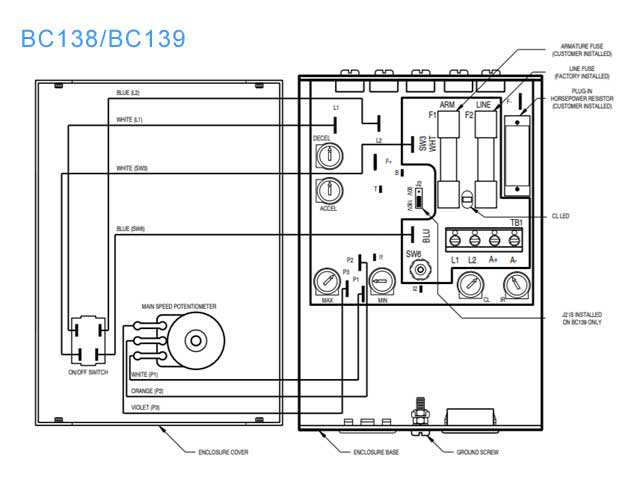
Here's what they're showing for internal drive diagram:


Baldor BC138 BC139 Drive
#26
Also, here's the troubleshooting guide for BC138 and BC139 drives

1. Motor does not run: AC input voltage not present at L1, L2 terminals. Verify correct wiring, Blown line fuse or tripped circuit breaker,  Blown armature fuse or control
circuit fuse. Replace blown fuse with SL-40 or equivalent. If fuse blew due to miswiring, power bridge module may be defective.

2. Motor is not running. Power ON LED is illuminated: Check ENABLE or INHIBIT circuit for loose or disconnected wiring, Main speed pot is set to zero. (Re-adjust to desired speed), Main speed pot, speed reference signal input, or motor connections are open (Verify there are no loose or disconnected wires).

3. Motor hums or runs at very low speed (Motor slows when load is applied). CL LED is illuminated: Incorrect motor wiring (Verify correct wiring), Motor is overloaded (Check motor current with DC ammeter and reduce load), Motor may be defective (Check motor for shorts or grounds), Check brushes, Current Limit (CL) trimpot may not be set correctly (Re-adjust CL trimpot).

4. Motor runs at high speed and does not respond to main speed pot or speed reference signal: Check field wiring, if using tachometer feedback, check tachometer signal.

The Baldor operator's manual is pretty simple, not alot there.
#27
Can you use a 400V motor with 480V?

We are having a discussion at work about a used motor we have. It is rated at 400V 50HZ. We have incoming power of 480V 60HZ and we are debating whether or not it will last. Has anyone had experience using 400V motors on a 480V system?