News:

Obsolete industrial electronics forum is still alive and well, just undergoing some maintenance and more anti spam stuff, stand by for a better experience

Main Menu
Menu

Show posts

This section allows you to view all posts made by this member. Note that you can only see posts made in areas you currently have access to.

Show posts Menu

Messages - wrenchturner

#1
Durant SERIES 1000 Trouble Shooting

If the Series 1000 Electronic Control does not perform satisfactorily the connections at the rear terminals should be checked first. If no loose wires or wiring errors are found remove all wires from the rear terminals and proceed through the following steps.

If the Control fails to function in any of the steps return it to Durant Digital Instruments, 901 S. 12th St., Watertown, Wi. 53094, Attn: Repair Dept. for repair with a letter describing the malfunction.

POWER INPUT:
Connect 120V.A.C. to terminals 12 and 14. The pilot light should be lit.
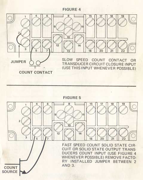
COUNT:
Make a momentary connection between terminals 5 and 7. While the connection is made the pilot light should be noticeably dimmer. Make a connection with a short piece of wire between terminals 2 and 3 and repeat the count test between terminals 5 and 7, the pilot light should change intensity. Retain the connection between terminals 2 and 3.

PREDETERMINED:
Set the Predetermined Setting at 0005. Interrupt the 120 V power to the control for a short time (about 2 seconds). Make a momentary connection between terminals 5 and 7 at least 5 times. You should hear the output relay actuate.
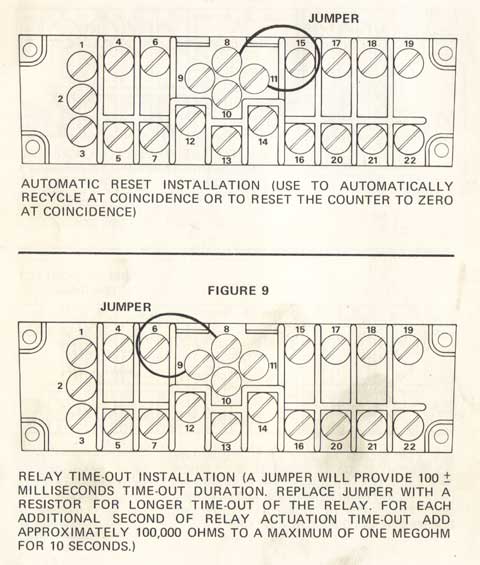
RELAY TIME OUT:
With the output relay actuated from the predetermined test make a connection between terminals 8 and 9. You should hear the output relay release.
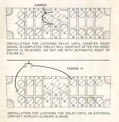
UNLATCH:
With the output relay actuated from the predetermined test make a momentary connection between terminals 7 and 15. You should hear the output relay release.

LATCH UNTIL RESET COMPLETE (LURC):
Make a connection between terminals 8 and 10 and actuate the output relay by performing the predetermined test. You should hear the output relay release when you release the reset switch after depressing it.

AUTO RECYCLE:
Make a connection between terminals 8, 9, and 11. Set the Prede­termined Setting at 0005, interrupt the 120 V power for a short time and make repeated momentary connections between terminals 5 and 7. You should hear the output relay actuate and release every 5 counts.
#2
Parallel Counters


WIRE FIRST CONTROL PER STEPS 1 THRU 6 OF PAGE 12.
SECOND SERIES 1000 CONTROL FIGURE 12 FIRST SERIES 1000 CONTROL

WIRE SECOND CONTROL PER STEPS 1, 2, 4, 5 and 6 DESCRIBED IN WIRING INSTRUCTIONS PAGE 12 and MAKE THE ABOVE CON­NECTIONS FOR COUNT INPUT FOR THE SECOND CONTROL IN PLACE OF STEP #3 of PAGE 12.
#3


AUTOMATIC RESET INSTALLATION (USE TO AUTOMATICALLY RECYCLE AT COINCIDENCE OR TO RESET THE COUNTER TO ZERO AT COINCIDENCE)

INSTALLATION FOR LATCHING RELAY UNTIL COUNTER RESET SIGNAL IS COMPLETED. (RELAY WILL DROP OUT AFTER THE RESET SWITCH IS RELEASED. DO NOT USE WITH AUTOMATIC RESET OF FIGURE 8.)


RELAY TIME-OUT INSTALLATION (A JUMPER WILL PROVIDE 100 + MILLISECONDS TIME-OUT DURATION. REPLACE JUMPER WITH A RESISTOR FOR LONGER TIME-OUT OF THE RELAY. FOR EACH ADDITIONAL SECOND OF RELAY ACTUATION TIME-OUT ADD APPROXIMATELY 100,000 OHMS TO A MAXIMUM OF ONE MEGOHM FOR 10 SECONDS.)
INSTALLATION  FOR  LATCHING THE RELAY UNTIL AN EXTERNAL CONTACT (CIRCUIT) CLOSURE IS MADE.


#4


COUNT CONTACT
SLOW SPEED COUNT CONTACT OR TRANSDUCER CIRCUIT CLOSURE INPUT (USE THIS INPUT WHENEVER POSSIBLE)

COUNT INVERT INSTALLATION (USE THIS CONNECTION WITH FIGURE 4 or 5 WHEN COUNT IS TO BE ENTERED AT THE END OF A CONTACT CLOSURE OR WHEN A CIRCUIT CHANGES TO THE HIGH [OPEN COLLECTOR] STATE)


FAST SPEED COUNT SOLID STATE CIR­CUIT OR SOLID STATE OUTPUT TRANS­DUCERS COUNT INPUT (USE FIGURE 4 WHENEVER POSSIBLE) REMOVE FACTO­RY INSTALLED JUMPER BETWEEN 2 AND 3.

USE TERMINALS 18, 21 AND 19, 22 IF THE EQUIPMENT IS TO BE TURNED "ON" WHEN THE COUNTER REACHES THE NUMBER SE­LECTED ON THE BI-DIRECTIONAL SWITCHES. USE TERMINALS 18, 21 AND 17, 20 IF THE EQUIPMENT IS TO BE TURNED "OFF".


#5
WIRING INSTRUCTIONS


Figure 1, should be used to sketch all the desired functional connections to be made to the control prior to making the actual connections.

Connect input power per Figure. 2. (Note: Counter not fused) Connect remote reset, if required, per Figure 3.
Connect count input per Figure 4 or 5 and/or 6. (Transducer wiring see Page 20)


Connect the equipment to be controlled by the predetermined number of counts, as selected on the bi-directional switches per Figure 7. Connect jumper for automatic reset if required per Figure 8.

Connect the jumpers as shown on Figures 9 or 10 or 11 to select the control desired for the relay output.
If a second Series 1000 is to be used as an additional control, wire the count output from the first Series 1000 to the count input of the second control as shown in Figure 12. Wire steps 2 thru 6 above omitting step 3 for the second control. (See Page 18) Schematic on Page 10 and 11.

NOTE: All Series 1000 controls have factory installed jumpers for Automatic Reset (Terminals 8 to 11) and 100 Millisecond time out (Terminals 8 to 9) and slow speed count input (Terminals 2 to 3). Remove jumpers if not required.

#6
I will post some of the manual for the Durant 1000 series counters. This is my random contribution to the forum here. I have installed and replaced tons of these counters early in my career. These counters are long obsolete...


GENERAL DESCRIPTION

The Series 1000 2, 3 or 4 digit, single level, Solid State Count/Control is a high noise immunity, solid state LED count display control using CMOS (Complementary Metal Oxide Semiconductor) integrated circuits and Durant bi-directional pushbutton selector switches.

The input circuit allows for selection of, and is optimized for, slow speed contact closures, for high speed solid state inputs and for a wide variety of transducers.

The input will accept all Durant transducers; shaft encoder 39300-XXX; miniphotocell 39200-400; retro-reflective photocell 49160-401; rotary and lineal contactor ES9513-RS; mercury wetted reed switch sensor 49485-400; zero speed vane pickup sensor 39400-400; and the proximity sensor 49434-400.

The count input can be inverted so that a count is entered when initiated or at the end of the count input. (When a photocell light beam is interrupted or when the light beam is re-established.)

The output consists of a relay with two 10 ampere 120VAC or 28VDC form "C" contacts. The relay operates in various modes selected by jumpers on the rear panel terminals. Relay operating modes which can be selected are: latch until reset signal is complete; latch until an external contact is closed or 100 millisecond time out.

The timeout duration can be increased up to 10 seconds by substituting a resistor for the rear panel terminal jumper.

The Series 1000 has a front panel reset switch and rear panel terminals are provided for a remotely located reset switch. Automatic reset at coincidence can be selected at the rear panel terminal by using a jumper.

Automatic reset provides for automatic recycling of the control without loss of counts, automatic reset at coincidence to permit measurement of the overshoot or over count after coincidence, etc.

SPECIFICATIONS

I.   Power Requirements

120VAC +10% - -20% 50/60 Hertz. Power is connected to the rear panel terminals provided, including chassis ground.
The power circuit is connected directly to the input power transformer primary without power switch or fusing.
Nominal wattage for a 4 digit unit is 6 watts with display, 5 watts without display. Maximum current is 0.1 amp with display, 0.08 without display.

II.   Counter and Coincidence

A.   Number of digits: 2, 3 or 4.
B.   Coincidence selection: Bi-directional switches.
C.   Characteristics:
Turn on to all zeros. (Higher order zeros blanked.)
Reset must override count.
Coincidence with count input only.
Display of power "ON" by LED indicator and change in the LED
light intensity as manual contact closure count inputs are made.
D.   Counter reset functions:
Front panel switch (depression of a momentary toggle switch).
External contact (circuit) closure to power supply common.
Automatic recycle with coincidence. (Jumper recycle terminal to
+15VDC.)

Maximum  immunity to reset contact bounce, contact noise or
external electrical noise (Schmitt Trigger reset input).
When  reset switches are used to terminate the relay actuation
output, the output is to terminate with the release of the switch
(latch until reset is completed).

III.     Output Control

A. Two form "C" contacts rated 10 amperes resistive at 120VAC or 28VDC.
B.   Output relay functions selectable at rear terminals. Timed 100 milliseconds (jumper time out terminal and+15VDC)
variable to 10 seconds (with external resistance added between time out terminal and +15VDC).

Latch   until   reset   is   completed   (jumper   LURC   terminal   to +15VDC). Latch until external contact or circuit closure (unlatch terminal jumpered to common). This circuit has a Schmitt Trigger input.

C.   Count output is provided to operate a second Series 1000 control or other logic circuit. This output assures compatibility of any other unit even with variations in production and short on or off time for the count input. Count Inputs (Always connect count input between input terminal and common.)

A.   Count circuit input to 5 kilohertz. Includes operation for most all
Durant transducers which are not better suited to slower count speed
of "B".

B.   Count  contact  closure to  150 hertz. To be used  in  all  Possible
Applications and  includes operation for  ES9513-RS, reed switch
49485-400, as well as slow speed encoder application, etc. (Count
input  is connected as indicated above and the "Low Frequency"
terminal must be jumpered to common.)

C.   Count invert. The count is entered when the contact is opened, the
photocell  goes dark, etc. (Connection is to be made between the
"invert" terminal and common. Count input must be made per IV.

D.   Provide   15VDC   (plug  and  two  commons)   at  rear  terminal   for
Durant transducer operation. To be rated for 100 milliampere output
at 15V +0.5, -2.0 VDC full line and load regulation.

V.       Rear Panel Terminals

A.   Six terminals for form "C" relay output contacts.
B.   Output/input terminals.

1. Count input invert (jumper invert terminal to common).
2. 15VDC common.
3. Slow speed count (jumper low frequency terminal to common).
4. Count output (connect additional control count input terminal to this count output and jumper commons of both units).
5. Count input (for both slow and high speed counting, connect count input between count input terminal and common).
6. 15VDC positive   (added terminal to facilitate wiring).
7. 15VDC common (added terminal to facilitate wiring).
8.
9. Timed output (jumper time out terminal to +15VDC for 100 milliseconds or add resistor in lieu of jumper, for time out up to 10 seconds).
10. Latch until reset is complete (jumper LURCterminal to+15VDC).
11. Auto recycle (jumper auto reset terminal to +15VDC).
15. Latch until external contact closure or circuit is made (connect switch or circuit between unlatch terminal and common).
17. Counter reset (connect remote reset switch between reset terminal and common).

VI.   Displays

A.   .300 inch LED count display.
B.   Optional decimal point of LED count display optionally availab
C.   Power "ON" and counting LED indicator. In this case an LED
lite is to operate with power "ON" and to reduce in intensity
count input so that counting is visually apparent at low speed m;
count contact closures.
D.   Ripple blanking of higher order zeros.

VII.   Weight

Chassis maximum volume is 64 cubic inches. The weight is 3 pou for the Series 1000 and 1.2 pounds for the desk mount chassis.


#7
Electrical and Electronic / Re: 480V Contactor Coils
September 04, 2015, 04:07:AM
I have worked on old manual machine tools where the start stop buttons were 480V and never like doing so. It seems like a recipe for disaster. If I were updating controls, I would personally change (or have them changed) to a safer working voltage. If an inexperienced maintenance person ever got his hands in there without knowing the machine well, it could have some pretty serious results. Just my two cents...