News:

Obsolete industrial electronics forum is still alive and well, just undergoing some maintenance and more anti spam stuff, stand by for a better experience

Main Menu
Menu

Show posts

This section allows you to view all posts made by this member. Note that you can only see posts made in areas you currently have access to.

Show posts Menu

Messages - zigmund

#1
Troubleshooting 101 / A06B DC Servo Faults
April 23, 2024, 03:57:AM
Here is a list of Fanuc alarms for the A06B-6047-*. DC Servo stuff for your DC problems. The DC axis faults are nagging problems sometimes, hopefully this helps with A06B troubleshooting.
 
(Some applicable part numbers: A06B-6047-H003, A06B-6047-H203, A06B-6047-H041, A06B-6047- H201, A06B-6047- H208, A06B-6047-H001, A06B-6047- H005, A06B-6047- H004, A06B-6047- H040)


  • What is NC Fault on Fanuc 6047? It means: Overload The Overload alarm occurs if the motor current exceeds the current required to actuate the thermal relay. Or if the power transformer thermostat or the regenerative discharge unit thermostat operates

  • What is TGLS Fault on Fanuc 6047? It means: Tacho Generator   The Motor speed exceeds the specified upper limit due to a break in in the velocity feedback wire, the TGLS indicator goes on. The motor is stopped by the dynamic brake.

  • What is OVC Fault on Fanuc 6047? It means: Over Current The Motor current exceeds the specified upper limit for more than the fixed period ( about 600 msec), the OVC indicator goes on. The motor is stopped by the dynamic brake.

  • What is BRK Fault on Fanuc 6047? It means: Circuit Breaker The Abnormal current exceeding the rating limit of the breaker is applied to the motor, the circuit breaker operates. The motor is stopped by the dynamic brake.

  • What is HVAL Fault on Fanuc 6047? It means: Over Voltage The AC input voltage applied to the servo transformer  exceeds the allowable value, the HVAL indicator goes on.  The motor is stopped by the dynamic brake.

  • What is HCAL Fault on Fanuc 6047? It means: Low Voltage The AC power source voltage drops abnormally, the LVAL indicator goes on. The motor is stopped by the dynamic brake.

  • What is DCA Fault on Fanuc 6047? It means: DC IssueThere is Abnormal current applied to the transistor bridge circuit, the HCAL indicator goes on. The motor is stopped by the dynamic brake.

#2
Series 0 Servo Faults and Alarm Codes

This is a general list of servo alarms (servo faults) that should be applicable to the following Fanuc series servos: Fanuc 0M-C, Fanuc 0M-F, Fanuc 00M-C, Fanuc 0M-D, Fanuc 0M-F, Fanuc 0M-C, Fanuc 0T-C, Fanuc 0T-F, Fanuc 0T-C, Fanuc 0TT-C, Fanuc 0T-D,  Fanuc 0TT-C, Fanuc 0C, 0-T and 0-M. These servo errors, servo faults, and alarms are not always common, but the whole list is here and hopefully this will help you out.

  • Q: What is a Fanuc 400 Alarm code on a 0-T or 0-M? A: SERVO ALARM: 1, 2TH AXIS OVERLOAD : 1-axis, 2-axis overload signal is on.

  • Q: What is a Fanuc 401 Alarm code on a 0-T or 0-M? A: SERVO ALARM: 1, 2TH AXIS VRDY OFF : 1-axis, 2-axis servo amplifier READY signal (DRDY) went off.

  • Q: What is a Fanuc 402 Alarm code on a 0-T or 0-M? A: SERVO ALARM: 3, 4TH AXIS OVERLOAD : 3 axis, 4 axis overload signal is on.

  • Q: What is a Fanuc 403 Alarm code on a 0-T or 0-M? A: SERVO ALARM: 3, 4TH AXIS VRDY OFF : 3-axis, 4 axis servo amplifier READY signal (DRDY) went off.

  • Q: What is a Fanuc 404 Alarm code on a 0-T or 0-M? A: SERVO ALARM: n-TH AXIS VRDY ON : Even though the n-th axis ( axis 1-8) READY signal ( DRDY) is still on. Or, when the power was turned on, DRDY went on even though MCON was off.

  • Q: What is a Fanuc 405 Alarm code on a 0-T or 0-M? A: SERVO ALARM: ZERO POINT RETURN FAULT: Position control system fault.

  • Q: What is a Fanuc 406 Alarm code on a 0-T or 0-M? A: SERVO ALARM: 7, 8TH AXIS OVERLOAD : 7TH, 8TH AXIS VRDY OFF
    7-axis, 8-axis overload signal is on.

  • Q: What is a Fanuc 4n0 Alarm code on a 0-T or 0-M? A: SERVO ALARM: n-TH AXIS -EXCESS ERROR: The position deviation value when the n-th  axis stops is larger than the set value.

  • Q: What is a Fanuc 4n1 Alarm code on a 0-T or 0-M? A: SERVO ALARM: n-AXIS-EXCESS ERROR : The position deviation value when the n-th axis stops is larger than the set value.

  • Q: What is a Fanuc 4n3 Alarm code on a 0-T or 0-M? A: SERVO ALARM: n-th AXIS -LSI OVERFLOW : The contents of the error register for the n-th axis exceeded power.

  • Q: What is a Fanuc 4n4 Alarm code on a 0-T or 0-M? A: SERVO ALARM: n-TH AXIS DETECTION RELATED ERROR : N-th axis digital servo system fault.

  • Q: What is a Fanuc 4n5 Alarm code on a 0-T or 0-M? A: SERVO AALRM: n-TH AXIS- EXCESS SHIFT : A speed higher than 4000000 units/s was attempted to be set in the n-th axis.

  • Q: What is a Fanuc 4n6 Alarm code on a 0-T or 0-M? A: SERVO ALARM: n-TH AXIS -DISCONNECTION : Position detection system fault in the n-th axis pulse coder ( dis-connection alarm).

  • Q: What is a Fanuc 4n7 Alarm code on a 0-T or 0-M? A: SERVO ALARM: n-TH AXIS-PARAMETER INCORRECT : This alarm occurs when the n-th axis is in one of the conditions: 1. The value set in Parameter no 8n20 (motor form) is out of the specified limit.
    2.  A proper value ( 111 or -111) is not set in parameter no 8n22.( motor revolution direction).
    3. Illegal data ( a value below 0, etc) was set in parameter No 8n23 ( number of speed feedback pulses per motor revolution) 4. Illegal data ( a value below 0, etc) was set in parameter No 8n24 ( number of speed feedback pulses per motor revolution) Parameters No. 8n84 and No. 8n85 (flexible field gear rate) have not been set.
    4. An axis selection parameter ( from No.269 to 274 is incorrect.
    5. An overflow occurred during parameter computation.

  • Q: What is a Fanuc 490 Alarm code on a 0-T or 0-M? A: SERVO ALARM: 5TH AXIS OVERLOAD : 5-axis, 6-axis overload signal is on.

  • Q: What is a Fanuc 491 Alarm code on a 0-T or 0-M? A: SERVO ALARM: 5, 6TH AXIS VRDY ON : 5-axis, 6-axis servo amplifier READY signal (DRDY) went off.

  • Q: What is a Fanuc 494 Alarm code on a 0-T or 0-M? A: SERVO ALARM: 5, 6TH AXIS VRDY ON : The axis card ready signal ( MCON) for axes 5 and 6 is off, but the servo amplifier ready signal (DRDY) is not. Alternatively when the power is applied, the DRDY is on and the MCON is not.

  • Q: What is a Fanuc 495 Alarm code on a 0-T or 0-M? A: SERVO ALARM: 5, 6TH AXIS ZERO POINT RETURN : This is a position control circuit error.

#3
SERIES 0 SYSTEM ALARMS

This is a general list of system alarms for the following Fanuc series controls: Fanuc 0M-C, Fanuc 0M-F, Fanuc 00M-C, Fanuc 0M-D, Fanuc 0M-F, Fanuc 0M-C, Fanuc 0T-C, Fanuc 0T-F, Fanuc 0T-C, Fanuc 0TT-C, Fanuc 0T-D,  Fanuc 0TT-C, Fanuc 0C, 0-T and 0-M. These faults, errors, and alarms are not always common, but the whole list is here and hopefully this will help you out.

  • Q: What is a Fanuc 910 Alarm code on a 0-T or 0-M? A: MAIN RAM PARITY : This RAM parity error is related to low-order-by-test.

  • Q: What is a Fanuc 911 Alarm code on a 0-T or 0-M? A: MAIN RAM PARITY : This RAM parity error is related to the low-order bytes..

  • Q: What is a Fanuc 912 Alarm code on a 0-T or 0-M? A: SHARED RAM PARITY :This RAM parity error is related to the low-order bytes of RAM shared with the digital servo circuit..

  • Q: What is a Fanuc 913 Alarm code on a 0-T or 0-M? A: SHARED RAM PARITY : This parity error is related to high-order bytes of RAM shared with the digital servo circuit..

  • Q: What is a Fanuc 914 Alarm code on a 0-T or 0-M? A: SERVO RAM PARITY : This is a local RAM parity error in the digital servo circuit..

  • Q: What is a Fanuc 915 Alarm code on a 0-T or 0-M? A: LADDER EDITING CASSETTE RAM PARITY : This RAM parity error is related to low order bytes of the ladder editing cassette..

  • Q: What is a Fanuc 916 Alarm code on a 0-T or 0-M? A: LADDER EDITING CASSETTE RAM PARITY : This RAM parity error is related to the high order bytes of the ladder editing cassette..

  • Q: What is a Fanuc 920 Alarm code on a 0-T or 0-M? A: WATCHDOG ALARM : This is a watchdog timer alarm or a servo system alarm for axis 1 to 4..

  • Q: What is a Fanuc 921 Alarm code on a 0-T or 0-M? A: SUB CPU WATCH DOG ALARM : This is a watchdog timer alarm related to the sub-CPU board or a servo system alarm for axis 5 or 6..

  • Q: What is a Fanuc 922 Alarm code on a 0-T or 0-M? A: 7/8 AXIS SERVO SYSYTEM ALARM : This is a servo system alarm related to axis 7 or 8..

  • Q: What is a Fanuc 930 Alarm code on a 0-T or 0-M? A: CPU ERROR : Replace the master PC board..

  • Q: What is a Fanuc 940 Alarm code on a 0-T or 0-M? A: PC BOARD INSTALLATION ERROR : PC board installation is incorrect. Check the specification of the PC board..

  • Q: What is a Fanuc 941 Alarm code on a 0-T or 0-M? A: MEMORY PC BOARD CONNECTION ERROR : The memory PC board is not connected securely..

  • Q: What is a Fanuc 945 Alarm code on a 0-T or 0-M? A: SERIAL SPINDLE COMMUNICATION ERROR : The hardware configuration is incorrect for the serial spindle, or a communication alarm occurred..

  • Q: What is a Fanuc 946 Alarm code on a 0-T or 0-M? A: SECOND SERIAL SPINDLE COMMUNICATION ERROR : Communication is impossible with the second serial spindle..

  • Q: What is a Fanuc 950 Alarm code on a 0-T or 0-M? A: FUSE BLOWN ALARM : A fuse has blown.

  • Q: What is a Fanuc 960 Alarm code on a 0-T or 0-M? A: SUB CPU ERROR : This is a sub-CPU error..

  • Q: What is a Fanuc 998 Alarm code on a 0-T or 0-M? A: ROM PARITY : This is a ROM parity error..

#4
I transposed these Fanuc spindle errors into Q&A style. Not sure if this is any more beneficial than the spindle fault list, but here it is anyway:

  • Q: What does Fanuc Spindle Alarm code 01 mean? A:  The inside temperature of the motor is higher than the specified temperature

  • Q: What does Fanuc Spindle Alarm code 02 mean? A:  The actual motor speed is largely deviated from the commanded speed

  • Q: What does Fanuc Spindle Alarm code 03 mean? A:  The fuse of the DC link has blown (The voltage at the DC link is insufficient) This alarm is checked when emergency stop is cancelled.

  • Q: What does Fanuc Spindle Alarm code 06 mean? A:  The temperature sensor is abnormal, or the temperature sensor cable is broken.

  • Q: What does Fanuc Spindle Alarm code 07 mean? A:  The motor rotates at a speed exceeding 115% (standard setting) of the maximum allowable speed.

  • Q: What does Fanuc Spindle Alarm code 09 mean? A:  The temperature of the heat sink of the SPM main circuit has risen abnormally. This alarm is issued for SPM-15i and later with SPM-2.2i to SPM-11i however, Alarm 12 is issued for the same cause.

  • Q: What does Fanuc Spindle Alarm code 12 mean? A:  An excessively large current flowed into the DC link of the main circuit.

  • Q: What does Fanuc Spindle Alarm code 15 mean? A:  In output switching control or spindle switching control, the switching operation sequence was not executed correctly.  This is issued if one second or more elapses from the transition of a switch request signal (SPSL or RSL) until a power lead state check signal (MCFN, MFNHG, RCH or RCHHG) makes a transition.

  • Q: What does Fanuc Spindle Alarm code 18 mean? A:  A sum check is abnormal.  If this alarm is issued, replace the SPM or SPM control printed-circuit board.

  • Q: What does Fanuc Spindle Alarm code 19 mean? A:  The offset voltage of the phase U (19) or phase V (20) current detection circuit is excessively high. A check is made when the power is turned on.

  • Q: What does Fanuc Spindle Alarm code 20 mean? A:  The offset voltage of the phase U (19) or phase V (20) current detection circuit is excessively high. A check is made when the power is turned on.

  • Q: What does Fanuc Spindle Alarm code 21 mean? A:  The specified polarity of the position sensor is incorrect.

  • What does Fanuc Spindle Alarm code 24 mean? A:  Serial communication data transferred between the CNC and spindle amplifier module contains an error.

  • Q: What does Fanuc Spindle Alarm code 27 mean? A:  The signal of the position code is disconnected.

  • Q: What does Fanuc Spindle Alarm code 29 mean? A:  An excessive load (standard setting: load meter reading of 9 V) has been applied continuously for a certain period (standard setting: 30 seconds).

  • Q: What does Fanuc Spindle Alarm code 31 mean? A:  The motor failed to rotate as specified, and has stopped or is rotating at a very low speed.

  • Q: What does Fanuc Spindle Alarm code 36 mean? A:  The error counter overflowed.

  • Q: What does Fanuc Spindle Alarm code 37 mean? A:  After emergency stop signal input, the motor is accelerated without being decelerated. This alarm is issued also when the motor is not deactivated (the motor is not decelerated completely) when the acceleration/deceleration time (initial parameter setting: 10 seconds) has elapsed after emergency stop signal input.

  • Q: What does Fanuc Spindle Alarm code 41 mean? A:  The position where the one-rotation signal of the position coder is generated is incorrect.

  • Q: What does Fanuc Spindle Alarm code 42 mean? A:  The one-rotation signal of the position coder is not generated.

  • Q: What does Fanuc Spindle Alarm code 46 mean? A:  The one-rotation signal of the position coder cannot be detected normally during thread cutting.

  • Q: What does Fanuc Spindle Alarm code 47 mean? A:  The count value of position coder signal pulses is abnormal. Phases A and B for the position coder have a feedback pulse count of 4096 p/rev per spindle rotation. The SPM checks the pulse counts of phases A and B equivalent to the position coder each time a one-rotation signal is generated. The alarm is issued when a pulse count beyond the specified range is detected.

  • Q: What does Fanuc Spindle Alarm code 50 mean? A:  A value obtained by internal calculation in spindle synchronization exceeded the allowable range.

  • Q: What does Fanuc Spindle Alarm code 52 mean? A:  The synchronization signal (ITP) in communication data transferred to and from the CNC stopped.

  • What does Fanuc Spindle Alarm code 53 mean? A:  The synchronization signal (ITP) in communication data transferred to and from the CNC stopped.

  • Q: What does Fanuc Spindle Alarm code 54 mean? A:  A large current flowing in the motor for a long time was detected.

  • Q: What does Fanuc Spindle Alarm code 55 mean? A:  In spindle switching control or output switching control, a mismatch between the switching request signal (SPSL or RSL) and the power lead state check signal (MCFN, MFNHG, RCH, or RCHHG) continues during motor activation.

  • Q: What does Fanuc Spindle Alarm code 56 mean? A:  The cooling fan for the control circuit section has stopped.

  • Q: What does Fanuc Spindle Alarm code 66 mean? A:  An error occurred during communication (connector JX4) between spindle and amplifier.

  • Q:What does Fanuc Spindle Alarm code 69 mean? A:  This alarm can be issued only when Dual Check Safety is in use. The alarm occurs if, in safety signal mode C, the spindle motor rotation speed exceeds the safety speed.

  • Q: What does Fanuc Spindle Alarm code 70 mean? A:  This alarm can be issued only when Dual Check Safety is in use. The spindle amplifier connection status does not match the hardware setting.

  • Q: What does Fanuc Spindle Alarm code 71 mean? A:  This alarm can be issued only when Dual Check Safety is in use. A safety parameter error occurred.

  • Q:What does Fanuc Spindle Alarm code 72 mean? A:  This alarm can be issued only when Dual Check Safety is in use. The result of the spindle amplifier speed check does not match the result of the CNC check.

  • Q: What does Fanuc Spindle Alarm code 73 mean? A:  The signal of the motor sensor is disconnected.

  • Q: What does Fanuc Spindle Alarm code 74 mean? A:  This alarm can be issued only when Dual Check Safety is in use. The CPU test failed to end normally

  • Q: What does Fanuc Spindle Alarm code 75 mean? A:  This alarm can be issued only when Dual Check Safety is in use. An error occurred in the CRC test.

  • Q: What does Fanuc Spindle Alarm code 76 mean? A:  This alarm can be issued only when Dual Check Safety is in use. The spindle safety function has not been executed.

  • Q: What does Fanuc Spindle Alarm code 77 mean? A:  This alarm can be issued only when Dual Check Safety is in use. The result of the spindle amplifier axis number check does not match the result of the CNC axis number check.

  • Q: What does Fanuc Spindle Alarm code 78 mean? A:  This alarm can be issued only when Dual Check Safety is in use. The result of the spindle amplifier safety parameter check does not match the result of the CNC safety parameter check.

  • Q: What does Fanuc Spindle Alarm code 79 mean? A:  This alarm can be issued only when Dual Check Safety is in use. An abnormal operation was detected in the initial test.

  • Q: What does Fanuc Spindle Alarm code 81 mean? A:  The position where the one-rotation signal of the motor sensor is generated is incorrect.

  • Q: What does Fanuc Spindle Alarm code 82 mean? A:  The one-rotation signal of the motor sensor is not generated.

  • Q: What does Fanuc Spindle Alarm code 83 mean? A:  The SPM checks the pulse counts of phases A and B each time a one-rotation signal is generated. The alarm is issued when a pulse count beyond the specified range is detected.

  • Q: What does Fanuc Spindle Alarm code 84 mean? A:  The spindle sensor signal was disconnected.

  • Q:What does Fanuc Spindle Alarm code 85 mean? A:  The one-rotation signal of the spindle sensor occurred in an incorrect location.

  • Q: What does Fanuc Spindle Alarm code 86 mean? A:  No spindle sensor one-rotation signal occurred.

  • Q: What does Fanuc Spindle Alarm code 87 mean? A:  A spindle sensor signal is abnormal.

  • Q: What does Fanuc Spindle Alarm code 88 mean? A:  The heat sink cooling fan is not running.

  • Q: What does Fanuc Spindle Alarm code A mean? A:  The control program is not running. An error was detected when the control program was running.

  • Q: What does Fanuc Spindle Alarm code A1 mean? A:  The control program is not running. An error was detected when the control program was running.

  • Q: What does Fanuc Spindle Alarm code A2 mean? A:  The control program is not running. An error was detected when the control program was running.

  • What does Fanuc Spindle Alarm code b0 mean? A:  An error occurred in communication between amplifier modules (SPM, SVM and PSM).

  • Q: What does Fanuc Spindle Alarm code C0 mean? A:  An error occurred in serial communication data between the CNC and spindle amplifier module.

  • Q: What does Fanuc Spindle Alarm code C1 mean? A:  An error occurred in serial communication data between the CNC and spindle amplifier module.

  • Q: What does Fanuc Spindle Alarm code C2 mean? A:  An error occurred in serial communication data between the CNC and spindle amplifier module.

  • Q: What does Fanuc Spindle Alarm code C3 mean? A:  In spindle switching a mismatch is found between the switching request signal (SPSL) and the internal status of the motor/spindle sensor signal switching circuit (submodule SW).


#5
FANUC Alpha Spindle Module Error, Fault, Alarm List

Here is a list and related description specifically for the spindle modules. Some of these spindle module faults are very rare. This list should be complete, if anyone sees any errors or alarms missing, just speak up. Sometimes I miss a single alarm code, or even a certain group of errors. Here it is:

  • 01 - The inside temperature of the motor is higher than the specified temperature

  • 02 - The actual motor speed is largely deviated from the commanded speed

  • 03 - The fuse of the DC link has blown (The voltage at the DC link is insufficient) This alarm is checked when emergency stop is cancelled.

  • 06 -  The temperature sensor is abnormal, or the temperature sensor cable is broken.

  • 07 - The motor rotates at a speed exceeding 115% (standard setting) of the maximum allowable speed.

  • 09 - The temperature of the heat sink of the SPM main circuit has risen abnormally. This alarm is issued for SPM-15i and later with SPM-2.2i to SPM-11i however, Alarm 12 is issued for the same cause.

  • 12 - An excessively large current flowed into the DC link of the main circuit.

  • 15 - In output switching control or spindle switching control, the switching operation sequence was not executed correctly.  This is issued if one second or more elapses from the transition of a switch request signal (SPSL or RSL) until a power lead state check signal (MCFN, MFNHG, RCH or RCHHG) makes a transition.

  • 18 - A sum check is abnormal.  If this alarm is issued, replace the SPM or SPM control printed-circuit board.

  • 19 - The offset voltage of the phase U (19) or phase V (20) current detection circuit is excessively high. A check is made when the power is turned on.

  • 20 - The offset voltage of the phase U (19) or phase V (20) current detection circuit is excessively high. A check is made when the power is turned on.

  • 21 - The specified polarity of the position sensor is incorrect.

  • 24 - Serial communication data transferred between the CNC and spindle amplifier module contains an error.

  • 27 - The signal of the position code is disconnected.

  • 29 - An excessive load (standard setting: load meter reading of 9 V) has been applied continuously for a certain period (standard setting: 30 seconds).

  • 31 - The motor failed to rotate as specified, and has stopped or is rotating at a very low speed.

  • 36 - The error counter overflowed.

  • 37 - After emergency stop signal input, the motor is accelerated without being decelerated. This alarm is issued also when the motor is not deactivated (the motor is not decelerated completely) when the acceleration/deceleration time (initial parameter setting: 10 seconds) has elapsed after emergency stop signal input.

  • 41 - The position where the one-rotation signal of the position coder is generated is incorrect.

  • 42 - The one-rotation signal of the position coder is not generated.

  • 46 - The one-rotation signal of the position coder cannot be detected normally during thread cutting.

  • 47 - The count value of position coder signal pulses is abnormal. Phases A and B for the position coder have a feedback pulse count of 4096 p/rev per spindle rotation. The SPM checks the pulse counts of phases A and B equivalent to the position coder each time a one-rotation signal is generated. The alarm is issued when a pulse count beyond the specified range is detected.

  • 50 - A value obtained by internal calculation in spindle synchronization exceeded the allowable range.

  • 52 -  The synchronization signal (ITP) in communication data transferred to and from the CNC stopped.

  • 53 -  The synchronization signal (ITP) in communication data transferred to and from the CNC stopped.

  • 54 -  A large current flowing in the motor for a long time was detected.

  • 55 -  In spindle switching control or output switching control, a mismatch between the switching request signal (SPSL or RSL) and the power lead state check signal (MCFN, MFNHG, RCH, or RCHHG) continues during motor activation.

  • 56 - The cooling fan for the control circuit section has stopped.

  • 66 - An error occurred during communication (connector JX4) between spindle and amplifier.

  • 69 - This alarm can be issued only when Dual Check Safety is in use. The alarm occurs if, in safety signal mode C, the spindle motor rotation speed exceeds the safety speed.

  • 70 - This alarm can be issued only when Dual Check Safety is in use. The spindle amplifier connection status does not match the hardware setting.

  • 71 - This alarm can be issued only when Dual Check Safety is in use. A safety parameter error occurred.

  • 72 - This alarm can be issued only when Dual Check Safety is in use. The result of the spindle amplifier speed check does not match the result of the CNC check.

  • 73 - The signal of the motor sensor is disconnected.

  • 74 - This alarm can be issued only when Dual Check Safety is in use. The CPU test failed to end normally

  • 75 - This alarm can be issued only when Dual Check Safety is in use. An error occurred in the CRC test.

  • 76 - This alarm can be issued only when Dual Check Safety is in use. The spindle safety function has not been executed.

  • 77 - This alarm can be issued only when Dual Check Safety is in use. The result of the spindle amplifier axis number check does not match the result of the CNC axis number check.

  • 78 - This alarm can be issued only when Dual Check Safety is in use. The result of the spindle amplifier safety parameter check does not match the result of the CNC safety parameter check.

  • 79 - This alarm can be issued only when Dual Check Safety is in use. An abnormal operation was detected in the initial test.

  • 81 - The position where the one-rotation signal of the motor sensor is generated is incorrect.

  • 82 - The one-rotation signal of the motor sensor is not generated.

  • 83 - The SPM checks the pulse counts of phases A and B each time a one-rotation signal is generated. The alarm is issued when a pulse count beyond the specified range is detected.

  • 84 - The spindle sensor signal was disconnected.

  • 85 - The one-rotation signal of the spindle sensor occurred in an incorrect location.

  • 86 - No spindle sensor one-rotation signal occurred.

  • 87 - A spindle sensor signal is abnormal.

  • 88 - The heat sink cooling fan is not running.

  • A - The control program is not running. An error was detected when the control program was running.

  • A1 - The control program is not running. An error was detected when the control program was running.

  • A2 - The control program is not running. An error was detected when the control program was running.

  • b0 - An error occurred in communication between amplifier modules (SPM, SVM and PSM).

  • C0 - An error occurred in serial communication data between the CNC and spindle amplifier module.

  • C1 - An error occurred in serial communication data between the CNC and spindle amplifier module.

  • C2 - An error occurred in serial communication data between the CNC and spindle amplifier module.

  • C3 - In spindle switching a mismatch is found between the switching request signal (SPSL) and the internal status of the motor/spindle sensor signal switching circuit (submodule SW).

#6
I even transposed these into a Q&A style list, I don't know if this is beneficial or not, but here it is anyway. And what does the dot mean on the Fanuc display?

  • What does Alarm 1 mean on Fanuc A06B? A: Internal cooling fan stopped
  • What does Alarm 2 mean on Fanuc A06B? A: Control power supply under voltage
  • What does Alarm 5 mean on Fanuc A06B? A: DC link under voltage
  • ]What does Alarm 6 mean on Fanuc A06B? A: Overheat
  • What does Alarm 8 mean on Fanuc A06B? A: DC link current alarm (L axis)
  • What does Alarm 8. mean on Fanuc A06B? A: IPM alarm (L axis)
  • What does Alarm 9 mean on Fanuc A06B? A: DC link current alarm (M axis)
  • What does Alarm 9. mean on Fanuc A06B? A: IPM alarm (M axis)
  • What does a Blinking Display mean on Fanuc A06B? A: abnormal control power supply
  • What does Alarm A mean on Fanuc A06B? A: DC Link Current alarm (N axis)
  • What does Alarm A. mean on Fanuc A06B? A: IPM alarm (N axis)
  • What does Alarm b mean on Fanuc A06B? A: DC Inverter: Control Command Failure
  • What does Alarm c mean on Fanuc A06B? A: DC Inverter: Control Command Failure
  • What does Alarm d mean on Fanuc A06B? A: DC Inverter: Control Command Failure
  • ]What does Alarm F mean on Fanuc A06B? A: cooling fan stopped of the radiator
  • What does Alarm P mean on Fanuc A06B? A: Communication error between amplifier and module
  • What does Alarm U mean on Fanuc A06B? A: FSSB communication error (COP10B)
  • What does Alarm L mean on Fanuc A06B? A: FSSB communication error (COP10A)
#7
Here is a handy list of Fanuc A06B Alarms and fault codes. They are  critical for any A06B troubleshooting. And they are applicable to: A06B-6079, A06B-6080, A06B-6089, A06B-6090, A06B-6096, A06B-6114, A06B-6117, and possibly some other Fanuc servo drives.

Alarm Code    Description of Fault

  • 1 - Internal cooling fan stopped
  • 2 - Control power supply under voltage
  • 5 - DC link under voltage
  • 6 - Overheat
  • 8 - DC link current alarm (L axis)
  • 8. - IPM alarm (L axis)
  • 9    - DC link current alarm (M axis)
  • 9. - IPM alarm (M axis)
  • Blinking - abnormal control power supply
  • A - DC Link Current alarm (N axis)
  • A. - IPM alarm (N axis)
  • b - DC Inverter: Control Command Failure
  • c - DC Inverter: Control Command Failure
  • d - DC Inverter: Control Command Failure
  • F - cooling fan stopped of the radiator
  • P - Communication error between amplifier and module
  • U - FSSB communication error (COP10B)
  • L - FSSB communication error (COP10A)

#8
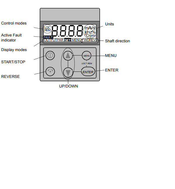
The ABB ACS160 is a reliable drive but even reliable drives are prone to faults and occasional alarms. The seven-segment display of the control panel indicates alarms and faults using codes "ALxx"
or "FLxx", where xx is the corresponding alarm or fault code. Errors are part of life with any brand and ABB keeps the display simple.

As a couple quick notes, the alarm and fault messages disappear when MENU, ENTER or the arrow buttons of control panel are pressed. The message will reappear after a few seconds if the keypad is not touched and the alarm or fault is still active.

Also the last three fault codes are stored into parameters 0128 to 0130. These faults can be cleared from the control panel by pressing UP and DOWN buttons at the same time in parameter set mode or through serial communication mode by writing 0 into them.

The faults can be reset either from the control panel (by pressing START/STOP button), by digital input (Parameter 1604) or serial communication, or switching the supply voltage off for a while. When the fault has been removed, the motor can be started. The ACS160 can be configured to automatically reset certain faults. This would be done in parameter group 31.
AUTOMATIC RESET. OK Here is the list of codes:

LIST OF ACS160 ALARMS

  • 1 * OPERATION FAILED Parameter upload or download failed. The software versions of the drives may not be compatible. Software version can be seen from parameter 3301 SOFTWARE VERSION.
  • 2 * START ACTIVE Control panel function is not allowed while start is active.
  • 3 * LOCAL/REMOTE Control panel function is not allowed in current control mode (local or remote). Control mode is local when LOC is displayed and remote mode when REM is displayed on the control panel.
  • 5 * BUTTON DISABLED Control panel function is denied for any of the following reasons: • START/STOP button is interlocked from digital input. This can happen with certain digital input configurations. Refer to section on Application Macros. • REVERSE button is locked because shaft direction is fixed by parameter 1003 DIRECTION. • The drive is in remote control mode and START/STOP and REVERSE buttons are not followed.
  • 6 * PARAM/LOCAL LOCK Control panel function is not allowed: • Parameter 1602 PARAMETER LOCK denies parameter editing • Parameter 1605 LOCAL LOCK denies local control mode.
  • 7 * FACTORY MACRO Control panel function is not allowed: Factory macro is selected and denies the parameter modifications. Factory macro is intended for applications where there is no control panel available.
  • 10 ** OVERCURRENT Overcurrent controller is active.
  • 11 ** OVERVOLTAGE Overvoltage controller is active.
  • 12 ** DC UNDERVOLTAGE Undervoltage controller is active.
  • 13 DIRECTION LOCK Rotation direction if fixed by parameter 1003 DIRECTION.
  • 14 SERIAL COMM LOSS Serial communication through Standard Modbus Channel is lost. • Check connections between external control system and the ACS160. • Refer to parameters 5204 COMM FAULT TIME and 5205 COMM FAULT FUNC.
  • 15 *, ** MODBUS EXCEPTION Exception response is sent through Standard Modbus channel. The bus master may be sending queries which cannot be processed by the ACS160. Last three exception response codes are stored into parameters 5213 - 5215.
  • 16 AI1 LOSS Analogue input 1 loss. Analogue input 1 value is less than MINIMUM AI1 (1301). See also parameter 3001 AI<MIN FUNCTION.
  • 17 AI2 LOSS Analogue input 2 loss. Analogue input 2 value is less than MINIMUM AI2 (1306). See also parameter 3001 AI<MIN FUNCTION.
  • 18 PANEL LOSS Panel communication loss. Control panel is disconnected when - Drive is in local control mode (LOC is shown in the control panel display), or  - Drive is in remote control mode (REM) and is parameterized to accept start/stop, direction or reference from the panel. Refer to parameters in groups 10 COMMAND INPUTS and 11 REFERENCE SELECT. See also parameter 3002 PANEL LOSS.
  • 19 ** ACS160 OVERTEMP ACS 160 overtemperature condition. This alarm is given when the temperature reaches 95% of the trip limit.
  • 20 MOTOR OVERTEMP Motor overtemperature condition as estimated by the ACS 160. Refer to parameters 3004 – 3008.
  • 21 UNDERLOAD Motor load is too low. Check for a problem in the driven equipment. Refer to parameters 3013 – 3015.
  • 22 MOTOR STALL Motor is operating in the stall region. This may be caused by excessive load or insufficient motor power. Refer to parameters 3009 – 3012.
  • 23 Reserved.
  • 24 Reserved.
  • 25 Reserved.
  • 26 ** OUTPUT OVERLOAD Inverter overload condition. The ACS 160 output current exceeds the ratings given in Reference Section P.
  • 27 * AUTOMATIC RESET ACS 160 is about to perform automatic fault reset operation. As a result, the drive may start after the reset operation. Refer to parameter group 31 AUTOMATIC RESET.
  • 28 * PID SLEEP PID sleep function is active. The drive may accelerate when PID sleep function is deactivated. Refer to parameters 4018 SLEEP SELECTION, 4013 PID SLEEP DELAY, 4014 PID SLEEP LEVEL nd 4015 WAKE-UP LEVEL.
  • 29 Reserved.
  • 30 Reserved.
  • 31 BR RES OVERLOAD Brake resistor is nearly overloaded. Refer to brake resistor instructions.

Pay attention to Notes!

Alarms (*) will not cause relay output RO1 (RO2) to activate when the relay output is configured to indicate alarm condition in general. (Parameter 1401 RELAY OUTPUT 1 (1402 RELAY OUTPUT 2) has value 5 (ALARM) or 13 (FLT/ALARM)).

Note! Alarms (**) will be shown only if parameter 1608 DISPLAY ALARMS is set to 1 (YES)

LIST OF ACS160 FAULTS

  • OVERCURRENT Output current is excessive. • Motor load may be too high • Acceleration time may be too short (parameters 2201 ACCELER TIME 1 and 2203 ACCELER TIME 2). • Motor or motor cable is faulty or connected wrong.
  • 2 DC OVERVOLTAGE Intermediate circuit DC voltage is excessive. • Check mains for static or transient overvoltages • Deceleration time may be too short (parameters 2202 DECELER TIME 1 and 2204 DECELER TIME 2) • Brake chopper (if present) may be underdimensioned
  • 3 ACS160 OVERTEMP ACS160 heat sink temperature is excessive. Temperature trip limit is 105 degree C. • Check air flow and fan operation. • Check motor power against unit power.
  • 4 ** SHORT CIRCUIT Fault current. Possible reasons for this fault are: • There is a short-circuit in the motor cable(s) or motor • Supply disturbances
  • 5 OUTPUT OVERLOAD Inverter overload condition. The ACS 160 output current exceeds the ratings given in Reference Section P.
  • 6 DC UNDERVOLTAGE Intermediate circuit DC voltage is not sufficient. • Mains phase may be missing • Fuse may be blown
  • 7 ANALOGUE INPUT 1 Analogue input 1 loss. Analogue input value is less than MINIMUM AI1 (1301). See also parameter 3001 AI<MIN FUNCTION.
  • 8 ANALOGUE INPUT 2 Analogue input 2 loss. Analogue input value is less than MINIMUM AI2 (1306). See also parameter 3001 AI<MIN FUNCTION.
  • 9 MOTOR OVERTEMP Motor overtemperature condition as estimated by the ACS 160. Refer to parameters 3004 – 3008.
  • 10 PANEL LOSS Panel communication loss. Control panel is disconnected when the drive is receiving start, stop and direction commands from the panel. - Drive is in local control mode (LOC is shown in the control panel display), or - Drive is in remote control mode (REM is shown) and is parameterised to accept start/stop, direction or reference from the panel. Refer to parameters in groups 10 COMMAND INPUTS and 11 REFERENCE SELECT. See also parameter 3002 PANEL LOSS.
  • 11 PARAMETERING Parameter values are inconsistent: • MINIMUM AI1 > MAXIMUM AI1 (parameters 1301, 1302) • MINIMUM AI2 > MAXIMUM AI2 (parameters 1304, 1305) • MINIMUM FREQ > MAXIMUM FREQ (parameters 2007, 2008)
  • 12 MOTOR STALL Motor stall. This may be caused by excessive load or insufficient motor power. Refer to parameters 3009 – 3012.
  • 13 SERIAL COMM LOSS Serial communication through Standard Modbus Channel is lost. • Check connections between external control system and the ACS160. • Refer to parameters 5204 COMM FAULT TIME and 5205 COMM FAULT FUNC.
  • 14 EXTERNAL FAULT SIGNAL External fault is active. See parameter 3003 EXTERNAL FAULT.
  • 15 ** OUTPUT EARTH FAULT Earth fault. The load on the incoming mains system is out of balance. • There may be a fault in the motor or motor cable. • Motor cable may be too long.
  • 16 ** DC BUS RIPPLE • Ripple voltages on the DC bus are too large. • Mains phase may be missing • Fuse may be blown

    • 17 UNDERLOAD Motor load is too low. Check for a problem in the driven equipment. Refer to parameters 3013 – 3015.
    • 18 Reserved
    • 19 Reserved.
    • 20 ** AI OUT OF RANGE Analogue input out of range. Check AI level.
    • 21 - 29 ** HARDWARE ERROR Hardware error. Contact supplier.
    • 30 BR RES OVERLOAD Brake resistor is overloaded. Refer to parameter 2005 OVERVOLT CTRL.
    • 31 ENCODER FAULT Positioning macro is used, but the drive is not receiving pulses. Check the encoder and its connections. Full display blinking Serial link failure. Bad connection between the control panel and the
      ACS 160.

    Pay attention to Note! Faults (**) are indicated by a red blinking LED and are reset by turning the power off for a while.

    Also there is plenty of other info for clearing ACS160 faults in the user manual if you have access to one.
#9
ABB ACS140 Fault, Alarm, and Error Codes

Alarm and Fault Displays

Here is some good general info from their service manual. The seven-segment display unit of control panel indicates alarms and faults using codes "ALxx" or "FLxx", where xx is the corresponding alarm or fault code. Alarms 1-7 arise from button operation. Green LED blinks for AL10-21, meaning that the ACS140 cannot fully follow the control commands. The faults are indicated by red LED. The alarm and fault messages disappear by pressing MENU, ENTER or the arrow buttons of the control panel. The message will reappear after a few seconds if the keypad is not touched and the alarm or fault is still active. Last three fault codes are stored into parameters 0128-0130. These fault memories can be cleared from the control panel by pressing UP and DOWN buttons simultaneously in parameter set mode.

ACS140_keypad

Fault Resetting

When the red LED of the ACS140 is on or blinking, a fault is active!!!

When the green LED of the ACS140 is blinking, an alarm is active!!!

Resetting or clearing a fault is half the battle, the other hand is clearing the error and removing the problem all together. Faults that are indicated by a red blinking LED are reset by turning the power off for a while. Other faults (indicated by red static LED) can be reset either from the control panel, by digital input or serial communication, or switching the supply voltage off for a while. When the fault has been removed, the motor can be started. The ACS140 can be configured to automatically reset certain faults. Refer to parameter group 31 AUTOMATIC RESET.


It is important to remember that if an external source for start command is selected and is still active, the ACS140 may start immediately after a fault reset.


ALARM CODE LIST

  • AL 1 Parameter upload/download failed.
  • AL 2 Operation not allowed while start is active.
  • AL 3 Operation not allowed in current control mode (Local or Remote).
  • AL 5 Start/Stop/Direction or reference from control panel is not followed. Possible causes: ï Remote mode: parameters disable the buttons (See APPENDIX.) ï Local mode: START/STOP button interlocked from digital inputs.
  • AL 6 Operation not allowed. Parameter 1602 PARAMETER LOCK is active.
  • AL 7 Use of factory macro disables operation.
  • AL10* Overcurrent controller active.
  • AL11* Overvoltage controller active.
  • AL12* Undervoltage controller active.
  • AL13 Direction lock. See parameter 1003 DIRECTION.
  • AL14 Serial communication loss alarm, see ACS140 RS485 and RS232 Adapter Installation and Start-up Guide.
  • AL15* Modbus exception response is sent through serial communication.
  • AL16 Analogue input 1 loss. Analogue input 1 value is less than MINIMUM AI1 (1301). See also parameters 3001 AI<MIN FUNCTION and 3013 AI1 FAULT LIMIT.
  • AL17 Analogue input 2 loss. Analogue input 2 value is less than MINIMUM AI2 (1306). See also parameters 3001 AI<MIN FUNCTION and 3014 AI2 FAULT LIMIT.
  • AL18* Panel loss. Panel is disconnected when Start/Stop/Dir or reference is coming from panel. See parameter 3002 PANEL LOSS and APPENDIX of manual.
  • AL19* Hardware overtemperature (at 95 % of the trip limit).
  • AL20* Motor overtemperature (at 95 % of the trip limit), see 3004 MOTOR THERM PROT.
  • AL21 Motor stall alarm. See parameter 3009 STALL FUNCTION.

Note! The Alarms marked with an asterisk  (*) will be shown only if parameter 1608 DISPLAY ALARMS is set to 1(YES) so you may not see them depending on your setting

-------------------


FAULT CODE LIST

  • FL 1 Overcurrent: ï Possible mechanical problem. Check for: Acceleration and/or deceleration times may be too short. OR Supply disturbances.
  • FL 2 DC overvoltage: Check for: Input voltage too high. OR Deceleration time may be too short.
  • FL 3 ACS140 overtemperature: Check for Ambient temperature too high. OR Severe overload.
  • FL 4 * Fault current: Check for: Output earth fault (200 V units). OR Short circuit. OR Supply disturbances.
  • FL 5 Output overload.
  • FL 6 DC undervoltage.
  • FL 7 Analogue input 1 fault. Analogue input 1 value is less than MINIMUM AI1 (1301). See also parameters 3001 AI<MIN FUNCTION and 3013 AI1 FAULT LIMIT.
  • FL 8 Analogue input 2 fault. Analogue input 2 value is less than MINIMUM AI2 (1304). See also parameters 3001 AI<MIN FUNCTION and 3014 AI2 FAULT LIMIT.
  • FL 9 Motor overtemperature. See parameters 3004-3008.
  • FL10 Panel loss. Panel is disconnected when Start/Stop/Dir or reference is coming from panel. See parameter 3002 PANEL LOSS and APPENDIX in manual. Note! If FL10 is active when the power is turned off, the ACS140 will start in remote control (REM) when the power is turned back on.
  • FL11 Parameters inconsistent. Possible fault situations: Check for MINIMUM AI1 > MAXIMUM AI1 (parameters 1301 and 1302) OR MINIMUM AI2 > MAXIMUM AI2 (parameters 1304 and 1305) OR MINIMUM FREQ > MAXIMUM FREQ (parameters 2007 and 2008)
  • FL12 Motor stall. See parameter 3009 STALL FUNCTION.
  • FL13 Serial communication loss.
  • FL14 External fault is active. See parameter 3003 EXTERNAL FAULT.
  • FL15 Output earth fault (400 V units).
  • FL16 * DC bus ripple too large. Check supply.
  • FL17 Analogue input out of range. Check AI level.
  • FL18 - FL22 * Hardware error. Contact supplier.
  • Full display blinking Serial link failure. Bad connection between the control panel and the ACS140. Check if the Serial communication parameters (group 52) have been altered. Keep panel connected and switch power off and then on again.

Note! Faults marked with an asterisk (*) are indicated by a red blinking LED are reset by turning the power off and on. Other faults are reset by pressing the START/STOP button. See also parameter 1604.

I'm sure this will be a big help for anyone troubleshooting the ACS140, Good Luck!
#10
ABB ACS100 Fault Codes and Alarm Help

From the ABB service manual I compiled a list of the ACS100 Fault codes or ACS100 Alarm codes, ACS100 Error codes, or whatever you like to call them. There's a lot of good information here regarding problem solving and clearing alarms on the ACS100. This list or errors will help you solve problems fast.

Alarm and Fault displays: The seven-segment display unit of control panel indicates alarms and faults using codes "ALxx" or "FLxx", where xx is the corresponding alarm or fault code. Alarms 1-6 arise from button operation.

Green LED blinks for AL10-16, meaning that the ACS 100 cannot fully follow the control commands. The faults are indicated by red LED.

The alarm and fault messages disappear by pressing MENU, ENTER or the arrow buttons of the control panel. The message will reappear after a few seconds if the keypad is not touched and the alarm or fault is still active. Last fault code is stored into parameter 102. This fault memory can be cleared from the control panel by pressing UP and DOWN buttons simultaneously in parameter set mode.

Resetting Faults (or alarms):

Faults that are indicated by a red blinking LED are reset by turning the power off for a while. Other faults (indicated by red static LED) can be reset either from the control panel, by digital input, or switching the supply voltage off for a while. When the fault has been removed, the motor can be started. The ACS100 can be configured to automatically reset certain faults. (This would be done with parameter 505 AUTO RESET which I don't cover here)

OK with that being said, here are the ACS100 faults/alarms to hopefully give you ACS100 troubleshooting help:

ACS100 ALARM CODE LIST

  • CF 0 Position of configuration switch S1. Certain parameters can be modified only when S1 = 0.
  • CF 1 Position of configuration switch S1. Certain parameters can be modified only when S1 = 0.
  • CF 2 Position of configuration switch S1. Certain parameters can be modified only when S1 = 0.
  • CF 3 Position of configuration switch S1. Certain parameters can be modified only when S1 = 0.
  • CF 4 Position of configuration switch S1. Certain parameters can be modified only when S1 = 0.
  • CF 5 Position of configuration switch S1. Certain parameters can be modified only when S1 = 0.
  • CF 6 Position of configuration switch S1. Certain parameters can be modified only when S1 = 0.
  • CF 7 Position of configuration switch S1. Certain parameters can be modified only when S1 = 0.
  • CF 8 Position of configuration switch S1. Certain parameters can be modified only when S1 = 0.
  • CF 9 Position of configuration switch S1. Certain parameters can be modified only when S1 = 0.
  • AL 1 Parameter upload/download failed.
  • AL 2 Operation not allowed while start is active.
  • AL 3 Operation not allowed in remote or local control.
  • AL 4 REVERSE button disabled. Parameter 208 (Dir Lock) is active.
  • AL 5 Panel START button disabled.
  • DI configuration is 3-wire and DI2 is open.
  • AL 6 Operation not allowed. Parameter 503 (Param Lock) is active.
  • AL10* Overcurrent controller active. Only shown only if parameter 506 is set to 1 (Yes).
  • AL11* Overvoltage controller active.Only shown only if parameter 506 is set to 1 (Yes).
  • AL12* Undervoltage controller active. Only shown only if parameter 506 is set to 1 (Yes).
  • AL13 Reserved. Contact supplier.
  • AL14 Reverse command attempted in remote control (REM), while parameter 208 (Dir Lock) is active.
  • AL15 Reserved. Contact ABB Motor supplier.
  • AL16 Reserved. Contact ABB Motor supplier.

ACS100 FAULT CODE LIST

Please Note that Faults (*) with red blinking LED are reset by turning the power off and on. The other faults are reset by pressing the START/STOP button. And here's the fault codes:

  • FL 1 Overcurrent: Possible mechanical problem or Acc and/or Dec times may be too small.
  • FL 2 DC overvoltage: Input voltage too high or Dec time may be too small.
  • FL 3 ACS 100 overtemperature: Ambient temperature too high or Severe overload.
  • FL 4 * Fault current: output earth fault or short circuit.
  • FL 5 Output overload.
  • FL 6 DC undervoltage.
  • FL 7 Analogue input fault. (See parameter 501.)
  • FL 8 Motor overtemperature. (See parameter 502.)
  • FL 9 Panel disconnected from drive in local control. Note! If FL 9 is active when the power is turned off, the ACS100 will start in remote control (REM) when the power is turned back on.
  • FL10 Parameters inconsistent. Check that AI min (fmin) is not greater than AI max (fmax).
  • FL11 * DC bus ripple too large. Check supply.
  • FL12 Reserved. Contact ABB motor/drive supplier.
  • FL13 * Hardware error. Contact ABB motor/drive supplier.
  • FL14 * Hardware error. Contact ABB motor/drive supplier.
  • FL15 * Analogue input out of range. Check AI level.
  • FL16 * Hardware error. Contact ABB motor/drive supplier.
  • FL17 * Hardware error. Contact ABB motor/drive supplier.
  • FL18 * Hardware error. Contact ABB motor/drive supplier.
  • FL19 * Hardware error. Contact ABB motor/drive supplier.
  • Full display blinking - Serial link failure or Bad connection between the control panel and the ACS100.
#11
I believe the troubleshooting guide pertains to all these models:
  • ACS50-01N-01A4-1
  • ACS50-01N-02A2-1
  • ACS50-01N-01A4-2
  • ACS50-01N-02A2-2
  • ACS50-01N-04A3-2
  • ACS50-01N-07A6-2
  • ACS50-01N-09A8-2
  • ACS50-01E-01A4-1
  • ACS50-01E-02A2-1
  • ACS50-01E-01A4-2
  • ACS50-01E-02A2-2
  • ACS50-01E-04A3-2
  • ACS50-01E-07A6-2
  • ACS50-01E-09A8-2
#12
ABB ACS50 Faults,  Errors, and Alarms

Guys here's a quick and easy guide for troubleshooting ACS50 faults, errors, alarms or whatever you want to call them. Straight from the manual, the troubleshooting guide is simple on these.

ACS50 has two status indication LEDs, visible through the front cover. If the drive detects a problem, the red LED will blink. After fixing the problem, reset by switching the start signal off. If start is off already, turn it first on and then off again. See the list below for the fault codes (= the number of LED blinks).

Remember the basics, Green LED On and Red LED off, ACS50 operates normally
Green LED On and Red LED Blinking means the protective function has been activated. The number of blinks indicates the fault code.

Green LED Blinking and Red LED Blinking means the ACS50 will reset automatically within 3 seconds. Warning! Motor starts, if the start signal is on so be aware of this.  Automatic reset will function if the AUTORESET is ON. This is configured using the DIP switches.

Ok here's the possible causes and what to do:

  • 1. DC overvoltage. 1) Mains voltage is too high: Check supply. 2) Deceleration ramp time is too short compared to the load. Automatic reset will function if the AUTORESET is ON
  • 2. DC undervoltage. Mains voltage is too low: Check supply. Automatic reset will function if the AUTORESET is ON
  • 3. Output short circuit: Switch off the power and check the motor windings and motor cable.
  • 4. Output overcurrent. 1) Acceleration time is too short compared to the load inertia: Increase ACC/DEC time with potentiometer. 2)Motor and drive sizes do not match: Check motor.
  • 5. Reserved
  • 6. Analogue input value is less than 4 mA/2 V. (*) Note: This supervision is active if AI OFFSET is ON.
  • 7. Motor overload (I2t overload): 1) Check the load, and verify that the motor size is suitable for ACS50. 2) Verify that setting of MOTOR I NOM potentiometer is correct.
  • 8. Inverter overload or excessive internal temperature: 1) Load is too high or 2) drive cooling is insufficient.
  • 9. Other fault. Internal error. Turn power off and on again. If problem persists replace the unit
#13
Toshiba VF-AS1 Alarms and Faults
possible causes and the associated remedy. Hopefully this alarm code list
Here is a general list of Toshiba AS1 alarms and fault codes. Included are will help guide you in your troubleshooting.

  • OC1 / OC1P Description: Overcurrent during acceleration Causes:  The acceleration time ACC is too short, the V/F setting is improper, a restart signal is input to the rotating motor after a momentary stop, etc., a special motor (motor with a small impedance) is used, or manual torque boost ub is large.

    Remedy/Solutions:  Increase the acceleration time ACC,  Check the V/f parameter setting, Use UuS (Auto-restart) and UuC (Regenerative power ride-though control), Increase the carrier frequency CF,
    Decrease ub setting value, Decrease F50 (stall prevention level) to 130 as a guide, Increase CF (carrier frequency) setting value if it is set at lower value (2kHz or less), Check the cable and the motor for ground faults.
  • OC2 / OC2P Description: Overcurrent during deceleration Causes: The deceleration time dEC is too short, or there is a possible ground fault

  • OC3 / OC3P Description: Overcurrent during fixed speed Causes: The load fluctuates abruptly, the load is in an abnormal condition, or there is possibly a ground fault.

  • OCA1 Description: U-Phase arm short-circuit Causes: a main circuit element is defective on U Phase

  • OCA2 Description: V-Phase arm short-circuit Causes: a main circuit element is defective on V Phase

  • OCA3 Description:: W-Phase arm short-circuit Causes: a main circuit element is defective on W Phase

  • OCL Description: Loaded side overcurrent at start time Causes: The insulation of the output main circuit or motor is defective, The motor has too small impedance, The drive circuit board in the inverter was damaged.

  • OCr Description: Dynamic braking element overcurrent 200v 55kW or larger, 400V-90kW or larger Causes: • PB-PA/* circuit is shorted, A resistor with resistance smaller than the minimum allowable resistance is connected, Parameter Pb was set to 1 or 2 without connecting regenerative brake or with wire disconnected (with dynamic braking).

  • OH Description: Overheating Causes: The cooling fan does not rotate, The ambient temperature is too high, The vent is blocked up, A heat generating device is installed close to the inverter, The thermistor in the unit is disconnected.

  • OH2 Description: Thermal trip (stop command from external device) Causes: An input signal is impressed at control input terminal PTG for optional add-on cards, A thermal trip command (input terminal function: 46 or 47) is issued by an external control device.

  • OL1 Description: Inverter Overload  Causes: Rapid acceler on is operated, The DC braking amount is too large, The V/f setting is improper, A restart signal is input to the rotating motor after a momentary stop, The load is too large.
  • OL2 Description: Motor Overload  Causes: The V/f parameter is improperly set, The motor is locked up, Low-speed operation is performed, An excessive load is applied to the motor during operation .
  • OLr Description: Dynamic braking resistor overload  Causes: Rapid deceleration is operated, Dynamic braking is too large.
  • OP1 Description: Overvoltage during acceleration  Causes: the input voltage fluctuates abrormaly, the power supply has a capacity of 500KVA or more, A power factor improvement capacitor is opened and closed, A system using a thyrister is connected to the same power distribution line, A restart signal is input to the stop. etc.
  • OP2 Description: Overvoltage during deceleration  Causes: The deceleration time DEC is too short, The dynamic braking resistor has a considerably large resistance, Pb (Dynamic braking resistor) is OFF, Overvoltage limit operation F305 is OFF, The input voltage fluctuates abnormaly, The power supply has a capacity of 500kVA or more,  A power factor improvement capacitor is opened and closed, A system using a thyrister is connected to the same power distribution line.
  • OP3 Description: Overvoltage during fixed speed operation  Causes: The input voltage fluctuates abnormally, The power supply has a capacity of 500kVA or more, A power factor improvement capacitor is opened and closed, A system using a thyrister is connected to the same power distribution line, The motor is in a regenetive state because the load causes the motor to run at a frequency higher than the inverter output frequency, The undervoltage detection level F625 is too low..
  • Ot Description: Overtorque  Causes: Overtorque reaches to a detection level during operation, Stall prevention operation was performed continuously for a length of time longer than that set with F452 .
  • UC Description: Low current  Causes: The outout current decreased to a low-current delecton level during operation.
  • UP1 Description:  : Voltage drop in main circuit  Causes: The input voltage (in the main circuit) is too low, Momentary power failure occurs because undervoltage continues longer than undervoltage detection time F528.
  • E Description: Emergency stop

  • EEP1 Description: EEPROM error

  • EEP2 Description:  Initial read error

  • EEP3 Description:  Initial read error

  • EF1 Description: Ground fault

  • EF2 Description: Ground fault

  • EEPH0 Description: Output phase failure

  • Err1 Description: Input phase failure

  • Err2 Description: Main Unit RAM fault

  • Err3 Description: Main Unit ROM fault

  • Err4 Description: CPU Fault

  • Err5 Description: Interruption of operation command from external control device

  • Err6 Description: Gate Array fault

  • Err7 Description: Output current detector error

  • Err8 Description: Optional unit fault

  • Etn Description: Tuning Error

  • Etn1 Description: tuning detection error

  • Etn2 Description: Motor constant value error


This one is a work in progress, stand by...

#14
Troubleshooting 101 / Toshiba H9 Drive Alarms
September 10, 2023, 05:40:AM
Toshiba H9 Drive Alarms

This is a list of the available user-notification codes of the EOI display and provides information that assists the user in the event that a Fault is incurred. The User Notification codes are displayed as an indication that a system function or system condition is active (i.e., ATN, DB, and DBON). The code is displayed on the EOI for the duration of the activation.

An Alarm is an indication that a Fault is imminent if existing operating conditions continue unchanged.

A Trip is a safety feature (the result of a Fault) that disables the H9 ASD system and removes the 3-phase power to the motor in the event that a subsystem of the ASD is malfunctioning, or one or more of the variables listed exceeds its normal range (time and/or magnitude). Included critical items in the trip list are: Current, Voltage, Speed, Temperature, Torque, or Load.

These alarms apply to Toshiba H9 ASD models: VT130H9U2035, VT130H9U2055, VT130H9U2080, VT130H9U2110, VT130H9U2160, VT130H9U2220, VT130H9U2270, VT130H9U2330, VT130H9U2400, VT130H9U2500, VT130H9U2600, VT130H9U2750, VT130H9U210K,VT130H9U212K, VT130H9U4055, VT130H9U4080, VT130H9U4110, VT130H9U4160, VT130H9U4220, VT130H9U4270, VT130H9U4330, VT130H9U4400, VT130H9U4500, VT130H9U4600, VT130H9U4750, VT130H9U410K, VT130H9U412K, VT130H9U415K, VT130H9U420K, VT130H9U425K, VT130H9U430K, VT130H9U435K, VT130H9U440K

  • CM1 Comm1 Error -  Internal communications error - Caused by: Improperly programmed ASD, Improper communications settings, Improperly connected cables.
  • CM2 Comm2 Error - External communications error - Caused by:  Improperly programmed ASD, Improper communications settings, Improperly connected cables.
  • E Emergency Off -  Output signal from the ASD is terminated and a brake may be applied if so configured - Caused by: Stop|Reset pressed twice at the EOI, EOFF command received remotely, ASD reset required.
  • MOFF Main Under-Voltage - Under-voltage condition at the 3-phase AC input to the ASD - Caused by: Low 3-phase commercial voltage
  • OC Over-Current - ASD output current greater than F601 setting. - Caused by: Defective IGBT (U, V, or W), ASD output to the motor is connected incorrectly, ASD output phase-to-phase short, The ASD is starting into a spinning motor, Motor/machine jammed, Mechanical brake engaged while the ASD is starting or while running, Accel/Decel time is too short, Voltage Boost setting is too high, Load fluctuations, ASD operating at an elevated temperature
  • OH Overheat - ASD ambient temperature excessive. - Caused by: ASD is operating at an elevated temperature, ASD is too close to heat-generating equipment, Cooling fan vent is obstructed (see Mounting the ASD on pg. 15 of the service manual), Cooling fan is inoperative, Internal thermistor is disconnected.
  • OJ Timer -  Run-time counter exceeded - Caused by: Type Reset required; select Clear run timer
  • OLI ASD Overload -  Load requirement in excess of the capability of the ASD. - Caused by:  The carrier frequency is too high, An excessive load, Acceleration time is too short, DC damping rate is set too high, The motor is starting into a spinning load after a momentary power failure, The ASD is improperly matched to the application.
  • OLM Motor Overload -  Load requirement in excess of the capability of the motor. - Caused by: V/f parameter improperly set, Motor is locked, Continuous operation at low speed, The load is in excess of what the motor can deliver
  • OLR Resistor Overload - Excessive current at the Dynamic Braking Resistor - Caused by: Deceleration time is too short, DBR configuration improperly set
  • OP Over-Voltage - DC bus voltage exceeds specifications. - Caused by: ASD attempting to start into a spinning motor after a momentary power loss, Incoming commercial power is above the specified range, Decel time is too short,  Voltage spikes at the 3-phase input; install inductive filter, DBR required, DBR resistance value is too high, DBR function is turned off, Over-Voltage Stall feature is turned off, System is regenerating, Load instability, Disable the Ridethrough function (F302)
  • OT Over-Torque - Torque requirement is in excess of the setting of F616 or F617 for a time longer than the setting of F618. - Caused by: ASD is not correctly matched to the application, F616 or F617 setting is too low, Obstructed load.
  • POFF Control Under-Voltage - Under-voltage condition at the 5, 15, or the 24 VDC supply - Caused by: Defective Control board, Excessive load on power supply, Low input voltage.
  • PtSt Reference Point - Two speed-reference frequency setpoint values are too close to each other - Caused by: Two speed reference frequency setpoints are too close to each other (increase the difference).
  • UC Under-Current - With the Low-Current Trip (F610) parameter enabled, the output current of the ASD is below the level defined at F611 and remains there for a time longer than the setting of F612 - Caused by: Output current too low
#15
Troubleshooting 101 / Fanuc CNC Alarms for Series 0-
September 07, 2023, 04:45:AM
Fanuc Series -0 Alarms and Troubleshooting

Here is some good info from the Fanuc service manual, hopefully helps you guys out. Following is a list of alarms on applicable Fanuc Series:

FANUC Series 0- TC, 0- TC, FANUC Series 0- MC, 0- MC, FANUC Series 0- TF, 0- TF, FANUC Series 0- MF, 0- MF, Series 0- C, FANUC Series 0- TTC, 0- TTC, FANUC Series 0- GCC, 0- GCC, FANUC Series 0- GSC, 0- GSC, FANUC Series 0- TD, 0- TD Series 0, FANUC Series 0- MD, 0- MD, Series 0- D, FANUC Series 0- GCD, 0- GCD, Series 0- D, FANUC Series 0- GSD, 0- GSD, Series 0- D, FANUC Series 0- TD II, 0- TD II, Series 0- D, FANUC Series 0- MD II, 0- MD II, Series 0- D II, FANUC Series 0- GCD II, 0- GCD II, Series 0- D II, FANUC Series 0- GSD II, 0- GSD II, FANUC Series 00- TC 00- TC, FANUC Series 00- MC, 00- MC Series 00- C, Series 00, FANUC Series 00- GCC, 00- GCC, FANUC Series 0- Mate TC, 0- Mate TC, FANUC Series 0- Mate, MC 0- Mate, MC Series 0- Mate, C Series 0- Mate, FANUC Series 0- Mate, MF 0- Mate MF

  • POWER CANNOT BE SWITCHED ON - Check the LED on the input unit or power supply unit AI, If no power supply alarm is detected (the red "ALM" LED does not light, Check the input fuse of the input unit or power supply unit AI.

    Measure the voltage across the R and S terminals on the screw-on terminal strip of the input unit or at the connector CP1 of the power supply unit AI using a volt-ohm-milliammeter, and check whether 200 VAC is available. If the 200 VAC cannot be detected at connector CP1, check the corresponding circuit in the machine.

    If both the fuse and power supply voltage are normal, the printed--circuit board of the input unit or the power supply unit AI may be defective.
  • NO MANUAL OPERATION NOR AUTOMATIC OPERATION CAN BE EXECUTED - Execute the following procedure when no manual nor automatic operation is done: Check whether position display shows correct position, Check CNC status display, Check CNC internal status using diagnostic function
  • JOG OPERATION CANNOT BE DONE - Check whether position display is operating, Check CNC status display, Check internal status using Diagnostic funciton.
  • HANDLE OPERATION CANNOT BE DONE - Check another manual operation (JOG) is accepted, Check CNC status display.
  • AUTOMATIC OPERATION CANNOT BE DONE - Check manual operation is possible, Check the status of cycle start LED on machine operator's manual, Check status of CNC.

    When manual operation is either impossible, perform countermeasure, based on the previous item "Jog operation cannot be done". Confirm that a correct mode isselected according to the mode selectstatus of CNC status display. Also, by confirming the automatic operation status it is possible to identify cycle operation, feed hold and cycle stop state
  • CYCLE START LED SIGNAL HAS TURNED OFF - After cycle operation is started, then stopped, check as follows: Confirm cycle start LED on machine operator's panel, Confirm CNC's diagnostic function.
  • NO DISPLAY APPEARS ON THE SCREEN WHEN THE POWER IS SWITCHED ON
  • ALARM 85 (READER/PUNCHER INTERFACE ALARM) Parameters on reader/puncher interface are not correct. Check the following setting data and parameters. External I/O device or host computer is faulty. I/O board is faulty. Cable between NC and I/O device is faulty. Parameters on reader/puncher interface are not correct, Check the appropriate setting data and parameters.
  • ALARM 86 (READER/PUNCHER INTERFACE ALARM) Parameters on reader/puncher interface are not correct. Check the following setting data and parameters. External I/O device or host computer is faulty. I/O board is faulty. Cable between NC and I/O device is faulty. Parameters on reader/puncher interface are not correct, Check the appropriate setting data and parameters.
  • ALARM 87 (READER/PUNCHER INTERFACE ALARM) Parameters on reader/puncher interface are not correct. Check the following setting data and parameters. External I/O device or host computer is faulty. I/O board is faulty. Cable between NC and I/O device is faulty. Parameters on reader/puncher interface are not correct, Check the appropriate setting data and parameters.
  • REFERENCE POSITION DEVIATES
  • ALARM 90 (REFERENCE POSITION RETURN IS ABNORMAL) The CNC received one rotation signal at least one time when the axis is moving to the reference position at a speed higher than a speed equivalent
    to 128 pulses of position error amount(DGN800 to 807), note: When a pulse coder is used as the detection of the absolute position, the reference point can be established after the motor turns more than one rotation with the battery connected.
  • ALARM 3n0 (REQUEST FOR REFERENCE POSITION RETURN) Absolute position data in the serial pulse coder was lost. (This alarm will be generated when serial pulse coder is exchanged or position feedback signal cable of the serial pulse coder is disconnected)
  • ALARM 3n1 (ABSOLUTE PULSE CODER IS FAULTY) Absolute pulse coder, cable or servo module is faulty. Jiggle the feedback cable leading from the servomotor to the axis card. Note whether an alarm occurs. If an alarm occurs, replace the cable or replace the axis cable.
  • ALARM 3n2 (ABSOLUTE PULSE CODER IS FAULTY) Absolute pulse coder, cable or servo module is faulty. Jiggle the feedback cable leading from the servomotor to the axis card. Note whether an alarm occurs. If an alarm occurs, replace the cable or replace the axis cable.
  • ALARM 3n3 (ABSOLUTE PULSE CODER IS FAULTY) Absolute pulse coder, cable or servo module is faulty. Jiggle the feedback cable leading from the servomotor to the axis card. Note whether an alarm occurs. If an alarm occurs, replace the cable or replace the axis cable.
  • ALARM 3n4 (ABSOLUTE PULSE CODER IS FAULTY) Absolute pulse coder, cable or servo module is faulty. Jiggle the feedback cable leading from the servomotor to the axis card. Note whether an alarm occurs. If an alarm occurs, replace the cable or replace the axis cable.
  • ALARM 3n5 (ABSOLUTE PULSE CODER IS FAULTY) Absolute pulse coder, cable or servo module is faulty. Jiggle the feedback cable leading from the servomotor to the axis card. Note whether an alarm occurs. If an alarm occurs, replace the cable or replace the axis cable.
  • ALARM 3N6 (ABSOLUTE PULSE CODER IS FAULTY) Absolute pulse coder, cable or servo module is faulty. Jiggle the feedback cable leading from the servomotor to the axis card. Note whether an alarm occurs. If an alarm occurs, replace the cable or replace the axis cable.
  • ALARM 3n7 (ABSOLUTE PULSE CODER BATTERY IS LOW) This alarm is generated when absolute pulse coder battery becomes low. Replace the batteries in the battery box connected to the connector of axis
    cards (CPA9 for the 1st to 4th axis cards, CPA10 for the 5th/6th axis card, and CPA11 for the 7th/8th axis card) When a type B axis board is being used with a built-in absolute pulse coder and an "a" or "b" series amplifier, the battery is installed in the servo amplifier. In such a case, replace the battery as described in the appropriate manual supplied with the servo amplifier.
  • ALARM 3n8 (ABSOLUTE PULSE CODER BATTERY IS LOW)  This alarm is generated when absolute pulse coder battery becomes low. Replace the batteries in the battery box connected to the connector of axis
    cards (CPA9 for the 1st to 4th axis cards, CPA10 for the 5th/6th axis card, and CPA11 for the 7th/8th axis card) When a type B axis board is being used with a built-in absolute pulse coder and an "a" or "b" series amplifier, the battery is installed in the servo amplifier. In such a case, replace the battery as described in the appropriate manual supplied with the servo amplifier.
  • ALARM 3n9 (SERIAL PULSE CODER IS ABNORMAL) An error is generated in the control section of the serial pulse coder
  • ALARM 400 (OVERLOAD) Amplifier or overheat of motor is detected. Confirm the detail by the diagnostic function of CNC.
  • ALARM 401 (*DRDY SIGNAL TURNED OFF) Servo amplifier is not turned on or it turned off during operation.
  • ALARM 402 (OVERLOAD)  Amplifier or overheat of motor is detected. Confirm the detail by the diagnostic function of CNC.
  • ALARM 403 (*DRDY SIGNAL TURNED OFF) Servo amplifier is not turned on or it turned off during operation.
  • ALARM 404 (*DRDY SIGNAL TURNED ON) DRDY signal is turned on before MCON signal is turned on. Or DRDY is not turned off after MCON signal is turned off. Possible servo amplifier is faulty, between servo amplifier and axis card is faulty, axis card is faulty.
  • ALARM 405 (*DRDY SIGNAL TURNED ON) DRDY signal is turned on before MCON signal is turned on. Or DRDY is not turned off after MCON signal is turned off. Possible servo amplifier is faulty, between servo amplifier and axis card is faulty, axis card is faulty.
  • ALARM 406 (OVERLOAD)  Amplifier or overheat of motor is detected. Confirm the detail by the diagnostic function of CNC.
  • ALARM 490 (OVERLOAD)  Amplifier or overheat of motor is detected. Confirm the detail by the diagnostic function of CNC.
  • ALARM 491 (*DRDY SIGNAL TURNED OFF) Servo amplifier is not turned on or it turned off during operation.
  • ALARM 4n0 (EXCESSIVE POSITION ERROR AMOUNT DURING STOP)
  • ALARM 4n1 (EXCESSIVE POSITION ERROR DURING MOVE) Position error amount during movement (DGN 800 to 807) execeeds a value set by parameter 504 to 507, 639, 640, 7504, 7505.
  • ALARM 4n4 (DIGITAL SERVO SYSTEM IS ABNORMAL)
  • ALARM 4n6 (DISCONNECTION ALARM) Position detection signal line is disconnected or short-circuited.
  • ALARM 4n7 (DIGITAL SERVO SYSTEM IS ABNORMAL) Digital servo parameters are abnormal or are set incorrectly. Confirm the setting value of the following parameters: PRM 8n20 : Motor format number PRM 8n22 : Motor rotation direction PRM 8n23 : Number of pulses of velocity feedback PRM 8n24 : Number of pulses of position feedback PRM 0269 to 0274 : Servo axis number PRM 8n84 : Flexible feed gear ratio PRM 8n85 : Flexible feed gear ratio
  • ALARM 700 (OVERHEAT AT CONTROL SIDE) Because an ambient temperature of the control unit becomes high, a thermostat mounted on the back panel of NC functions and informs an alarm
  • ALARM 704 (SPINDLE SPEED FLUCTUATION DETECTION ALARM) This alarm indicates that the spindle speed has changed abnormally due to the load.
  • ALARM 408 (THE SPINDLE SERIAL LINK DOES NOT START NORMALLY.) : Indicates that, in a system using serial spindles, the spindle amplifier does not start normally when power is applied. This alarm will not occur once the system (including the spindle control unit) has started. It can occur before the system starts during power turn-on processing. Once the system has started, an error is indicated as system alarm 945.
  • ALARM 409 (SPINDLE ALARM) This alarm indicates, to the CNC, that in a system with serial spindles, an alarm has occurred in the spindle unit. The alarm is described using the AL-XX (where XX is a number) format Indicated on the spindle amplifier display. Setting bit 7 of parameter No. 0397 to 1 enables the display of the alarm number from the spindle on the alarm screen. This alarm is intended to indicate a failure in the spindle control unit. It is detailed below. The spindle should be repaired according to the procedure described for each alarm.
  • ALARM 998 (ROM PARITY ERROR) A ROM parity error has occurred.
  • ALARM 910 (RAM PARITY ERRORS) These alarms indicate RAM parity errors. RAM is provided with a check bit (parity bit). When data is written to RAM, the check bit is also written to the RAM by either setting it to 1 or resetting it to 0 so that the total number of 1 bits in the data, including the check bit, is even or odd. When the data is read from RAM, the check bit is used to ensure that the read data is correct.
  • ALARM 911 (RAM PARITY ERRORS)
  • ALARM 912 (RAM PARITY ERRORS)
  • ALARM 913 (RAM PARITY ERRORS)
  • ALARM 914 (RAM PARITY ERRORS)
  • ALARM 915 (RAM PARITY ERRORS)
  • ALARM 916 (RAM PARITY ERRORS)
  • ALARM 920 (WATCH DOG OR RAM PARITY) The timer used to monitor the operation of CPU is called the watch dog timer. The CPU resets timer time every time a constant time has passed. When an error occurs in CPU or peripheral device, timer is not reset but the alarm is informed.
  • ALARM 921 (WATCH DOG OR RAM PARITY) The timer used to monitor the operation of CPU is called the watch dog timer. The CPU resets timer time every time a constant time has passed. When an error occurs in CPU or peripheral device, timer is not reset but the alarm is informed.
  • ALARM 922 (WATCH DOG OR RAM PARITY) The timer used to monitor the operation of CPU is called the watch dog timer. The CPU resets timer time every time a constant time has passed. When an error occurs in CPU or peripheral device, timer is not reset but the alarm is informed.
  • ALARM 941 (INCORRECTLY INSTALLED MEMORY PRINTED--CIRCUIT BOARD) This alarm indicates the poor connection of a memory printed circuit board. Check that all connections are secure.
  • ALARM 930 (CPU ERROR) CPU error (abnormal interrupt) has generated. Main CPU board is faulty An interrupt which will not occur during usual operation has generated. Peripheral circuit of the CPU may be abnormal. Change the main CPU board. If operation is performed normally by power off and on, noise may be a cause.
  • ALARM 945 (SERIAL SPINDLE COMMUNICATION ERRORS)
  • ALARM 946 (SERIAL SPINDLE COMMUNICATION ERRORS)
  • ALARM 960 (SUB CPU ERROR) Sub-CPU printed circuit board defective. An interrupt that would not occur under a usual condition occurred. It is likely that a CPU peripheral circuit malfunctioned. Replace the sub-CPU printed circuit board. If a normal operation can be resumed by turning the power off and on again, the malfunction may have occurred due to noise
  • ALARM 950 (BLOWN FUSE) The +24E fuse has blown. An overcurrent has flowed through the +24E line, which is a 24V line used for the I/O printed circuit board and machine power magnetics circuit. There may be a short circuit between the 24V line and 0V in the machine or I/O cable. After removing the cause, replace fuse in the power supply unit.
#16
Yaskawa drives are somewhat popular,  Yaskawa Site has a bunch of new products listed.
#17
These drives were made by Electromotive Systems, Inc. (ESI)

They are a company based in Milwaukee, Wisconsin. ESI specializes in providing advanced electrical and electronic control systems for various industries, including locomotive and marine propulsion, industrial automation, crane control, and power generation. They offer a range of products and solutions, including motor control systems, electronic controls, power conversion equipment, and related services.

Not sure these drives are still around.
#18
Participating in an industrial forum can be a great way to engage with others who perform maintenance and share knowledge within a community. Here are some suggestions to improve your forum participation:

Read the guidelines: Familiarize yourself with the obsolete inductrial's guidelines and rules. Each forum may have specific rules regarding behavior, content, and posting etiquette. Adhering to these guidelines will help you contribute in a positive and respectful manner.

Contribute valuable content: Provide meaningful and helpful contributions to the forum discussions. Share your knowledge, experiences, and insights. Offer solutions or suggestions when appropriate. This will enhance the overall quality of the obsolete industrial forum and establish your credibility as a valuable contributor.

Stay on topic: Ensure your contributions are relevant to the discussion at hand. Avoid derailing threads or going off on tangents. If you want to discuss a different topic, consider starting a new thread.

Use proper formatting and grammar: Make your posts easy to read by using proper formatting, paragraphs, and punctuation. Double-check your grammar and spelling before posting to maintain clarity and professionalism.

Engage with others: Interact with other industrial maintenance techs by responding to their posts, asking questions, and showing genuine interest in their perspectives. Engaging in meaningful discussions fosters a sense of community and encourages others to participate as well.

Avoid self-promotion: While it's acceptable to share relevant links or resources, avoid excessive self-promotion or spamming the forum with promotional content. Focus on contributing value to the industrial community rather than solely promoting yourself or your business.

Use a constructive tone: When providing feedback or engaging in debates, maintain a constructive and diplomatic tone. Offer criticism respectfully and support your points with evidence or logical reasoning.

Report any issues: If you come across any inappropriate behavior or violations of forum rules at obsolete industrial, report them to the forum moderators or administrators. This helps maintain a healthy and positive environment for all participants.

Remember, active and constructive participation is key to a thriving forum community. By following these suggestions, you can contribute positively and make your forum experience more enjoyable for yourself and others.

Hopefully this is some valuable input for the OI forum
#19
Overall, these are reliable drives and shouldn't fault out all that often. The Yaskawa Z1000 is known for its energy-saving capabilities, precise motor control, and user-friendly design. Some notable features of the Z1000 include:

  • Energy Efficiency: The Z1000 incorporates advanced control algorithms and energy optimization features to help reduce energy consumption in HVAC systems. It can provide significant energy savings by matching motor speed and torque to the system requirements, resulting in reduced energy costs.
  • Built-in Harmonic Suppression: The Z1000 includes a built-in harmonic filter, which helps mitigate the adverse effects of harmonic distortion on power quality. This feature allows the drive to comply with power quality standards and helps prevent issues caused by harmonics in the electrical system.
  • Easy Installation and Configuration: The Z1000 is designed with user-friendly features to simplify installation and configuration. It includes an easy-to-use keypad interface with intuitive menus for drive setup and parameter adjustments. Additionally, it offers various communication options for seamless integration into building automation systems.
  • Robust Performance and Reliability: The Z1000 is engineered for reliable and efficient operation in demanding HVAC applications. It is built with high-quality components, robust construction, and protective features to ensure long-term performance and durability.
  • Comprehensive Protection and Diagnostic Features: The Z1000 offers a range of protection and diagnostic features to safeguard the drive and connected equipment. It includes motor overload protection, short circuit protection, phase loss protection, and fault diagnostics to help identify and troubleshoot issues quickly.

#20
Using two types of braking in harmony with each other may be the answer in many cases. Dynamic motor braking and mechanical brakes serve different purposes and can be used in combination to provide enhanced braking performance and safety.

Dynamic motor braking is a braking method that uses the motor itself to slow down the rotational motion of a driven load. It involves using the motor as a generator, converting the kinetic energy of the rotating load into electrical energy, which is then dissipated through resistors or returned to the power supply. Dynamic motor braking can help decelerate the load quickly and efficiently, especially in applications where frequent and precise braking is required.

However, dynamic motor braking may not provide sufficient stopping power or be suitable for all applications. It is typically more effective at lower speeds and may not be able to bring the load to a complete stop within a short period. Additionally, in situations where power loss or motor failure occurs, dynamic motor braking may not be available.

This is where mechanical brakes come into play. Mechanical brakes, such as disc brakes or drum brakes, provide direct physical contact with the load and are capable of stopping it quickly and reliably. Mechanical brakes can be applied manually, electrically, or pneumatically, depending on the specific application and requirements.

In certain scenarios, combining dynamic motor braking with a mechanical brake can offer enhanced safety and braking performance. The dynamic motor braking can be used for regular or controlled deceleration, while the mechanical brake serves as a backup or emergency braking mechanism to bring the load to a complete stop in case of motor or power failure.

The need for a mechanical brake in conjunction with dynamic motor braking depends on factors such as the load characteristics, required stopping time, safety considerations, and industry standards or regulations. It is important to assess these factors and consult with experts or follow equipment manufacturer recommendations to determine the most appropriate braking system for your specific application.
#21
I like the industrial parts classified ad idea. But there are some other effective ways to sell your extra parts also. There are several other options available to consider. Here are some of the best places I think to sell old industrial parts:

  • Online Marketplaces: Online marketplaces like eBay, Amazon, and Alibaba are popular platforms for buying and selling industrial parts. These platforms have a wide reach and attract buyers from around the world. You can create listings for your parts, set your own prices, and reach a large audience of potential buyers.
  • Industrial Equipment and Machinery Auctions: Participating in industrial equipment and machinery auctions is another option to sell your old industrial parts. These auctions attract buyers who are specifically interested in industrial equipment and parts. Look for local or online auctions that specialize in industrial machinery or parts to maximize your chances of finding interested buyers.
  • Online Classifieds and Forums: Utilize online classified platforms and industry-specific forums to advertise and sell your industrial parts. Platforms like Craigslist or industry-specific forums allow you to reach a targeted audience of potential buyers who are specifically interested in industrial equipment and parts.
  • Surplus Equipment Dealers: There are companies that specialize in buying and selling surplus industrial equipment and parts. These dealers can evaluate your parts and offer you a fair price based on their market value. Search for surplus equipment dealers in your area or consider reaching out to them online.
  • Local Industrial Suppliers or Repair Shops: Check with local industrial suppliers or repair shops to see if they have an interest in purchasing your old industrial parts. Sometimes, these businesses may be willing to buy used parts for repair or replacement purposes.

Before selling your old industrial parts, it is advisable to assess their condition, determine their market value, and consider any potential costs associated with shipping or handling.

Also, honesty is the best policy, providing clear and accurate descriptions, along with any relevant specifications or documentation, can help attract potential buyers and ensure a smooth selling process.
#22
Troubleshooting 101 / Re: How to Test Drive IGBT
April 30, 2023, 04:56:AM
Here's a cookie cutter explanation on testing an IGBT

An IGBT (Insulated Gate Bipolar Transistor) is a power semiconductor device used in many electronic devices such as inverters, motor drives, and power supplies. Here are the steps you can follow to test an IGBT:

  • Turn off the power: Before testing an IGBT, make sure that the power to the device is turned off and that the device has had enough time to discharge any capacitors.
  • Check for Short Circuits: Using a multimeter set to the resistance or continuity mode, check for short circuits between the IGBT's emitter, collector, and gate terminals. Any shorts should be repaired before further testing.
  • Check the Gate-Emitter Voltage: Using a multimeter set to the diode mode, measure the voltage between the gate and emitter of the IGBT. The voltage should be near zero when the gate is not conducting, and it should be around 0.6 to 0.7 volts when the gate is conducting.
  • Check the Collector-Emitter Voltage: Using a multimeter set to the diode mode, measure the voltage between the collector and emitter of the IGBT. The voltage should be near zero when the IGBT is not conducting, and it should be around the forward voltage drop of the device when it is conducting.
  • Check the Current Capacity: Using a suitable test setup, apply a suitable voltage and current to the IGBT and measure its current capacity. The current capacity should match the specifications provided by the manufacturer.
  • Check for Faults: While testing the IGBT, monitor for any signs of faults such as overheating, short circuits, or voltage spikes.

It is important to refer to the manufacturer's data sheet and application notes for specific testing procedures and parameters for the IGBT in question. Additionally, some advanced testing may require specialized equipment, such as an oscilloscope, to accurately measure the IGBT's performance. Good luck and happy IGBT'ing
#23
Troubleshooting 101 / Re: Thermal Switch Failure
April 30, 2023, 04:43:AM
Loose wire nuts can wreak havoc, simply because they create confusion. they cause:

Poor Electrical Contact: A loose wire nut can cause poor electrical contact between wires, which can lead to voltage drops, overheating, and arcing. This can result in flickering lights, intermittent power loss, and damage to the circuit components.

Short Circuits: If a loose wire nut causes two or more wires to touch, it can create a short circuit, which can result in the circuit breaker tripping or the fuse blowing. This can also damage the circuit components and create a fire hazard.

Overheating: A loose wire nut can cause increased resistance in the circuit, which can generate heat and cause the wires and components to overheat. This can lead to melting of the insulation and wires, which can create a fire hazard.

Electrical Noise: A loose wire nut can cause electrical noise in the circuit, which can interfere with the performance of other electrical devices and equipment.

It is important to regularly check and tighten wire nuts in electrical circuits to ensure that they are secure and not causing any problems. If you suspect that a loose wire nut is causing issues, it is important to turn off the power to the circuit and fix the problem immediately to prevent any further damage or hazards.

If your equipment is moving or vibrating you probably shouldn't be using wire-nuts in the first place, a crimp on termination or connector would be more suitable.
#24
Troubleshooting 101 / Re: YASKAWA A1000
April 30, 2023, 04:40:AM
Check the Motor: A faulty motor can cause problems with the drive's performance. Use a multimeter to test the motor's resistance and ensure that it is within the manufacturer's specifications.

If you're still unable to find the problem with your Yaskawa drive, it may be time to contact Yaskawa technical support they are available, and they help without too much of a headache.
#25
Magnetek is a pretty popular brand of AC drives that are commonly used in various industrial applications. Here are some of the most common faults that you may encounter while using Magnetek drives:

  • Overcurrent Fault: This fault occurs when the drive's output current exceeds the set limit, which can be caused by a mechanical overload, excessive motor load, or a short circuit in the motor wiring.
  • Overvoltage Fault: This fault occurs when the DC bus voltage exceeds the drive's limit, which can be caused by a sudden loss of load, regenerative energy, or input voltage fluctuations.
  • Undervoltage Fault: This fault occurs when the input voltage falls below the drive's minimum operating level, which can be caused by power supply issues or faulty wiring.
  • Overtemperature Fault: This fault occurs when the drive's internal temperature exceeds the set limit, which can be caused by poor ventilation, high ambient temperature, or excessive load.
  • Communication Fault: This fault occurs when there is a communication problem between the drive and the controller, which can be caused by a faulty communication cable, incorrect settings, or software issues.

It is important to consult the Magnetek drive user manual if you have one if any of these faults occur, as they can indicate serious issues that require immediate attention. Magnetek drives are designed with advanced diagnostic and fault monitoring features to help identify and troubleshoot faults quickly and efficiently. The menus are pretty easy to navigate.
#26
I was surprised to find a few free PLC software packages when I looked around. Here's what I found:

Siemens - Siemens offers a free version of their STEP 7 TIA Portal software, which is used for programming Siemens PLCs. The free version, called TIA Portal Basic, allows users to develop and test programs for small to medium-sized applications.

Rockwell Automation - Rockwell Automation offers a free version of their Studio 5000 Logix Designer software, which is used for programming Allen-Bradley PLCs. The free version, called Studio 5000 Logix Designer Lite, allows users to create, configure, and program small to medium-sized control systems.

Mitsubishi Electric - Mitsubishi Electric offers a free version of their GX Works3 software, which is used for programming Mitsubishi PLCs. The free version, called GX Works3 MELSOFT Start-up Navigation, allows users to create and simulate simple programs.

Omron - Omron offers a free version of their CX-One software, which is used for programming Omron PLCs. The free version, called CX-One Lite, allows users to develop and test programs for small to medium-sized applications.

WAGO - WAGO offers a free version of their e!COCKPIT software, which is used for programming WAGO PLCs. The free version, called e!COCKPIT Demo Version, allows users to create and test simple programs.

It is important to note that while these software versions are free, they may have limitations in terms of functionality or application size. Additionally, some companies may require users to register for access to the software.
#27
Here are some of the most common documented Vacon Faults, this my help somebody using these drives:

Overcurrent Fault: This fault occurs when the drive's output current exceeds the set limit, which can be caused by a mechanical overload, excessive motor load, or a short circuit in the motor wiring.

Overvoltage Fault: This fault occurs when the DC bus voltage exceeds the drive's limit, which can be caused by a sudden loss of load, regenerative energy, or input voltage fluctuations.

Undervoltage Fault: This fault occurs when the input voltage falls below the drive's minimum operating level, which can be caused by power supply issues or faulty wiring.

Overtemperature Fault: This fault occurs when the drive's internal temperature exceeds the set limit, which can be caused by poor ventilation, high ambient temperature, or excessive load.

Communication Fault: This fault occurs when there is a communication problem between the drive and the controller, which can be caused by a faulty communication cable, incorrect settings, or software issues.

It is important to consult the Vacon drive user manual and technical support if any of these faults occur, as they can indicate serious issues that require immediate attention. Vacon drives are designed with advanced diagnostic and fault monitoring features to help identify and troubleshoot faults quickly and efficiently.
#28
I put together a small list of the most frequent Powerflex 40 alarms based on documented experience with this drive:

The PowerFlex 40 is a popular compact AC drive manufactured by Allen Bradley, commonly used in various industrial applications. Here are some of the most common alarms that you may encounter while using the PowerFlex 40:

F005 - Overvoltage Fault: This alarm occurs when the DC bus voltage exceeds the drive's limit, which can be caused by a sudden loss of load, regenerative energy, or input voltage fluctuations.

F007 - Ground Fault: This alarm occurs when a ground fault is detected in the motor or motor wiring. It can be caused by a damaged motor insulation or faulty wiring.

F013 - Motor Overload: This alarm occurs when the motor current exceeds the drive's current limit, which can be caused by a mechanical overload or a motor fault.

F014 - Shorted SCR Fault: This alarm occurs when the drive's output SCR is shorted or damaged, which can be caused by high voltage spikes or excessive current.

F111 - Communication Fault: This alarm occurs when there is a communication problem between the drive and the controller, which can be caused by a faulty communication cable, incorrect settings, or software issues.

It is important to consult the PowerFlex 40 user manual and technical support if any of these alarms occur, as they can indicate serious issues that require immediate attention.
#29
I compiled a list of the most popular frequency drives that I am aware of, here you go:

ABB ACS880: The ABB ACS880 is a modular VFD that offers high performance, flexibility, and ease of use. It is suitable for a wide range of applications, including pumps, fans, and conveyors.

Siemens Sinamics G120: The Siemens Sinamics G120 is a compact VFD that offers advanced control features and high power density. It is ideal for use in industries such as water/wastewater, HVAC, and food and beverage.

Schneider Electric Altivar Process ATV600: The Schneider Electric Altivar Process ATV600 is a high-performance VFD that offers advanced control features, including predictive maintenance and cybersecurity. It is ideal for process applications such as pumping, mixing, and ventilation.

Danfoss VLT AutomationDrive FC 302: The Danfoss VLT AutomationDrive FC 302 is a versatile VFD that offers high performance and energy efficiency. It is suitable for a wide range of applications, including pumps, fans, and conveyors.

Yaskawa V1000: The Yaskawa V1000 is a compact and cost-effective VFD that offers advanced control features and energy efficiency. It is suitable for a range of applications, including HVAC, water/wastewater, and material handling.

Overall, these VFDs are popular due to their advanced features, flexibility, and reliability, making them suitable for a range of industries and applications.
#30
Are Fanuc Drives Still Relevant?

Yes, Fanuc drives are still relevant in today's industrial automation and motion control applications. Fanuc is a leading manufacturer of industrial automation equipment, and their drives are widely used in various industries such as automotive, aerospace, electronics, and more.

Fanuc drives offer several advantages, including high reliability, precise control, and flexibility. They are designed to work with a range of motors and offer advanced features such as torque control, speed control, and position control.

Moreover, Fanuc drives have been developed over the years to keep up with the changing requirements of the industry. They are available in various models, each designed to meet specific application needs, including AC drives, servo drives, and spindle drives.

Overall, Fanuc drives remain a popular choice for industrial automation and motion control applications due to their proven track record of reliability and performance, along with their advanced features and flexibility.

I haven't seen a Fanuc drive factory installed in any of the new equipment we bought that's why I asked but apparently Fanuc is still kickin'